Introduction
This book contains a set of tutorials showcasing several use cases where Kuwaiba can be applied effectively, as well as platform operation and development tips.
Modeling
DWDM Ring
This example takes three sites with DWDM multiplexers created from scratch and from a template, and connect them in a ring topology using the Object View and the Outside Plant Manager module.
VAS Platforms
This example showcases a way to model mobile VAS platforms. This is a beginner level example for users who wonder how to model applications and services.
5G and IOT Application
This guide provides a step-by-step tutorial on modeling 5G networks for IoT applications using the Kuwaiba tool. It demonstrates how to structure and manage network resources (RFS) supporting smart traffic lights and mobile internet services. The manual highlights flexible approaches to visualize and optimize 5G network topologies.
Platform Operation
Bulk Upload
This tutorial describes how to run one of the data on-boarding examples available in the code repository, and sketches the basics of data ingesting in Kuwaiba.
Development
Creating a New Module
This example demonstrates how to extend Kuwaiba by creating a module using the Integration API, and manage inventory objects using BusinessEntityManager.
DWDM Ring
Configuring the Templates
Templates are predefined, reusable containment structures. They can be created for any kind of element in the inventory, even physical connections, logical structures or services (as in Customer or Resource Facing Services). The Template Manager is available in the Administration menu. In this example, we are going to create a basic template for this multiplexer, which happens to have 15 slots in its biggest flavor.
First, open the Template Manager and search for the class you are going to create a template for, in this example, DWDMMux.
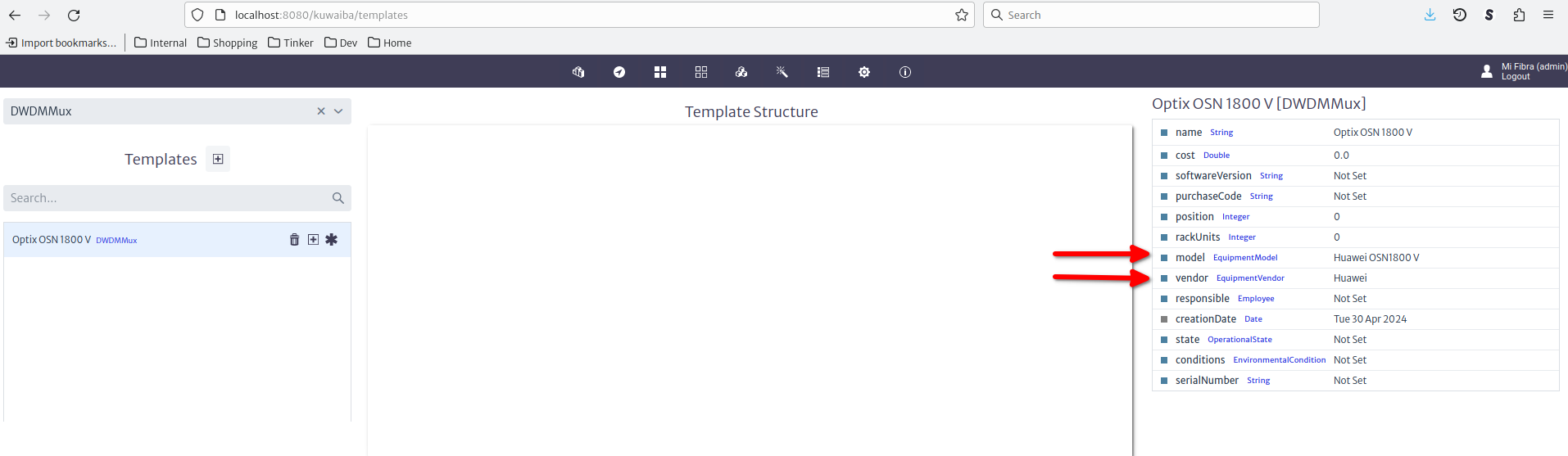
Set the default attribute values in the property sheet on the right. For this example, we had previously created a Huawei OSN1800 V entry in the EquipmentModel list type. To create the slots, use the "+" button next to your new template. Choose single or multiple according to your needs. If you chose multiple, use a pattern as instructed in the user manual. The inner elements are created from the "..." menu next to the parent object. In this example, we will create a control board in the first slot, and communications boards with single ports in the next 2.
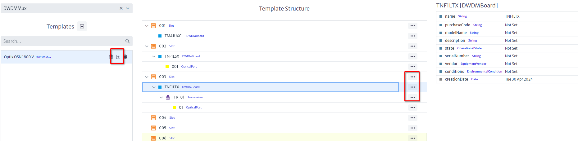
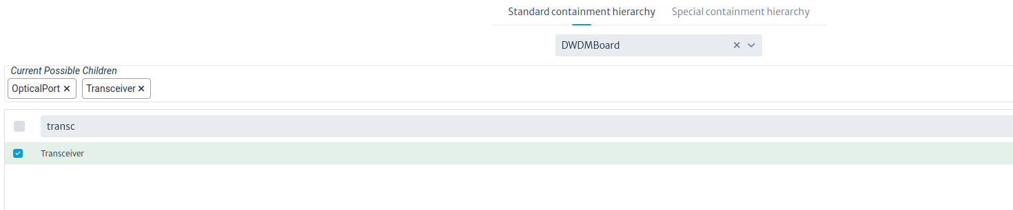
If you require SFPs, create them as Transceiver instances under the boards, and create a regular port under them. Change the containment configuration if required.
Creating the Devices
Now that we have a template, we are going to create three multiplexers in three different buildings. Note that we will just create one of them using a template, the other buildings will be copied and renamed from the original. The figure below shows a building with a room and a rack.
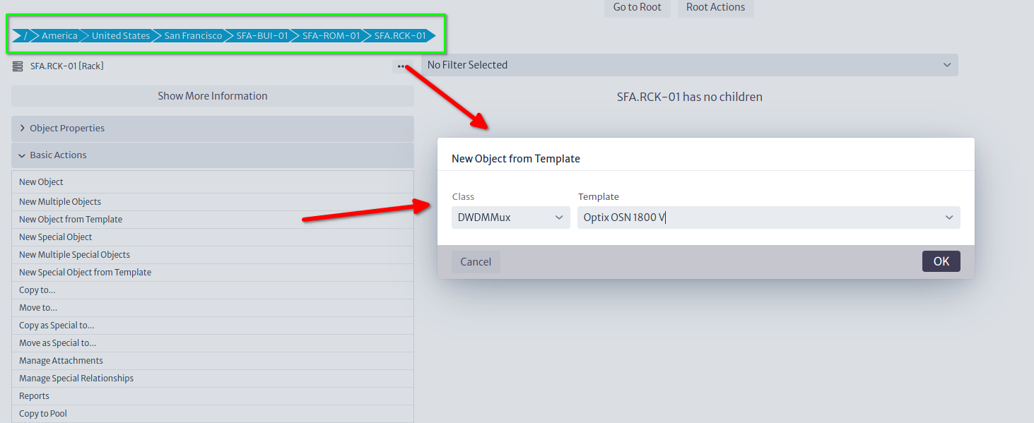
Now, from the rack we can launch the Create from Template action from the Basic Actions section, or the ... button next to the rack, and actually create the multiplexer. In the same rack we will place an ODF, also created from a template.
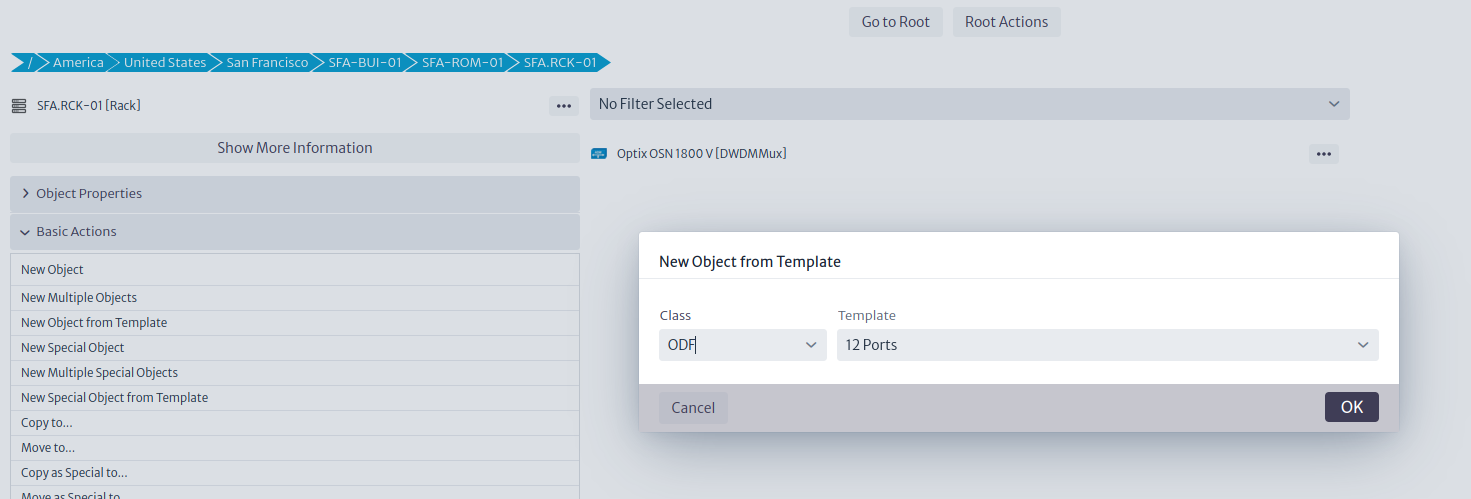
ODFs (and D/MDF for that matter) deserve a special mention. In Kuwaiba, distribution frames are modeled as elements with the same number of input and output ports, this emulates the tray that it's inside the ODF that serves as splicing point between the inbound fiber strands and the pigtails connected to the ports in the front of the panel. By default, input and output ports are disconnected, you have to connect them using what we call a mirror (see more details in the Physical Connections chapter of the User's Manual). This mirror, back-to-back connection between ports is useful to model several scenarios, but for now, we will use them only to represent a splicing function. Mirrors can be created in the template, but this feature is disabled in this version of Kuwaiba (it might be back later, but for now it's only available in the development version 2.5), so we'll have to create the mirrors once the ODF is created. Naming the ODF ports FRONT-XX/BACK-XX is not mandatory, but will simplify things later, as we will see.
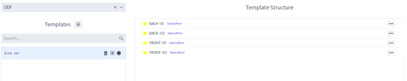
Now that the template is ready, we can create the ODF as a sibling of the multiplexer inside the rack.
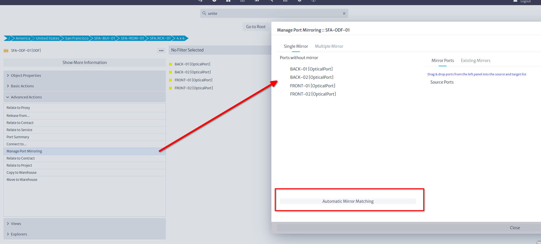
After the ODF has been created, we can mirror the ports by launching the Manage Port Mirroring action from the Advanced Actions menu. Click the Automatic Mirror Matching button and confirm the operation. This step is not precisely intuitive, but we'll re-evaluate UI in coming versions. This will leave the ODF ready to be connected.
Connecting the Devices
There are two types of connections in Kuwaiba: Containers and Links. The latter are anything that can connect two ports (fibers, coaxial/ethernet cables, telephonic pairs, power cables, etc). The former, as its name indicates, can contain other containers and links. To put it graphically, these are containers and these are links. You can find more information about both in the User's Manual. You can create your own types of both, but we won't get into that today. Suffice to say, that we will use containers (with fibers -OpticalLinks- inside) to connect buildings, and simple links (fibers) to connect devices in the same rack.
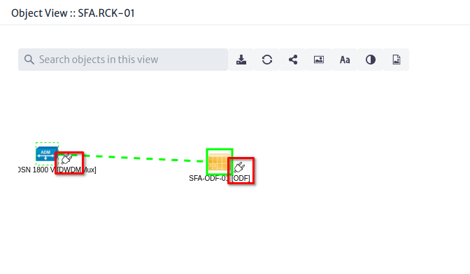
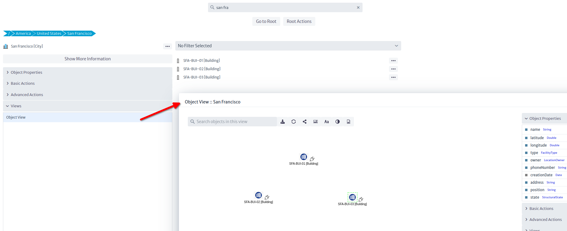
Let's start with the inside plant. There are several ways to create connections in Kuwaiba, but we are going to use the simplest method: The Object View. Select the rack and open the Views section, and click on Object View
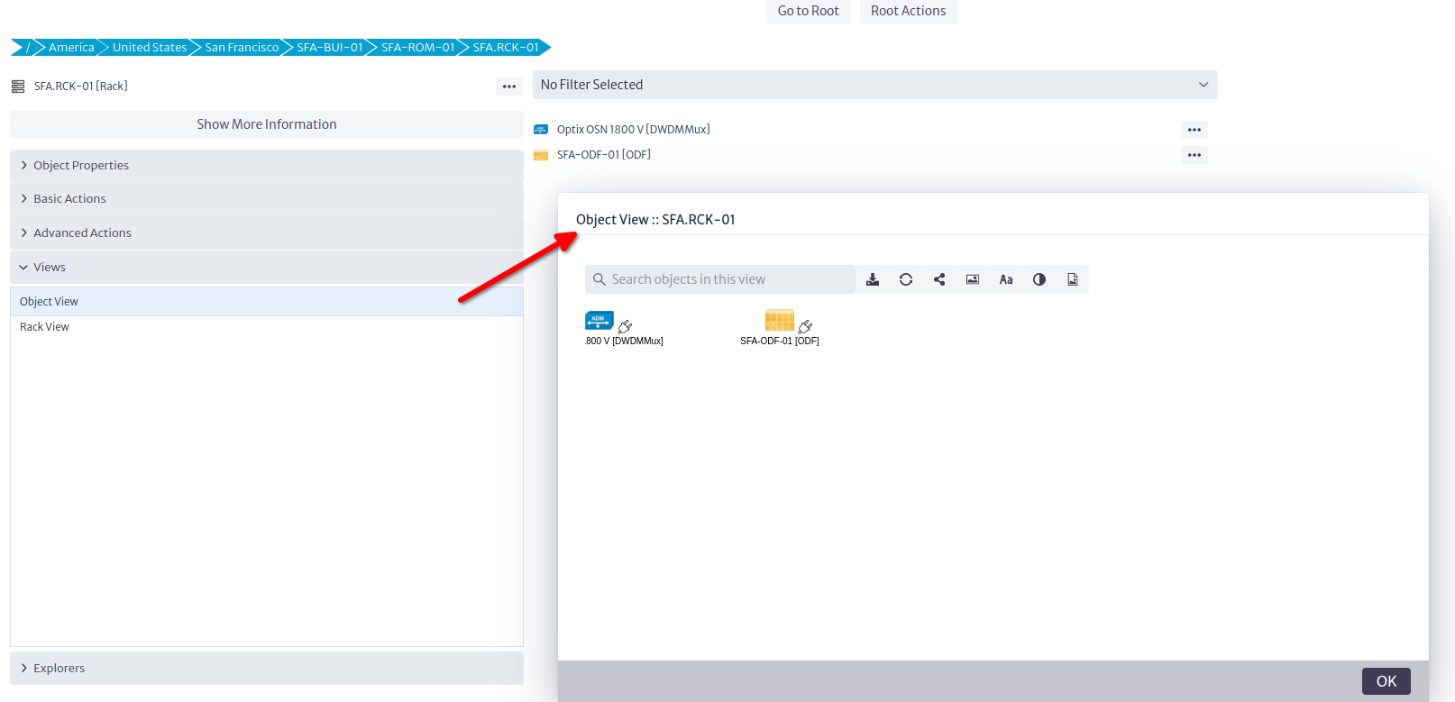
Views are graphical representations of selected objects (Other views are discussed in the User's Manual). The Object View is the simplest of these views, and shows the direct children of a given object, as well as their connections. You can add background images (for example floor plans in inside plant scenarios), connect elements and export the view, among other things. To connect the ODF and the multiplexer, click on the plug icon of any of the end points, and drag it to the target.
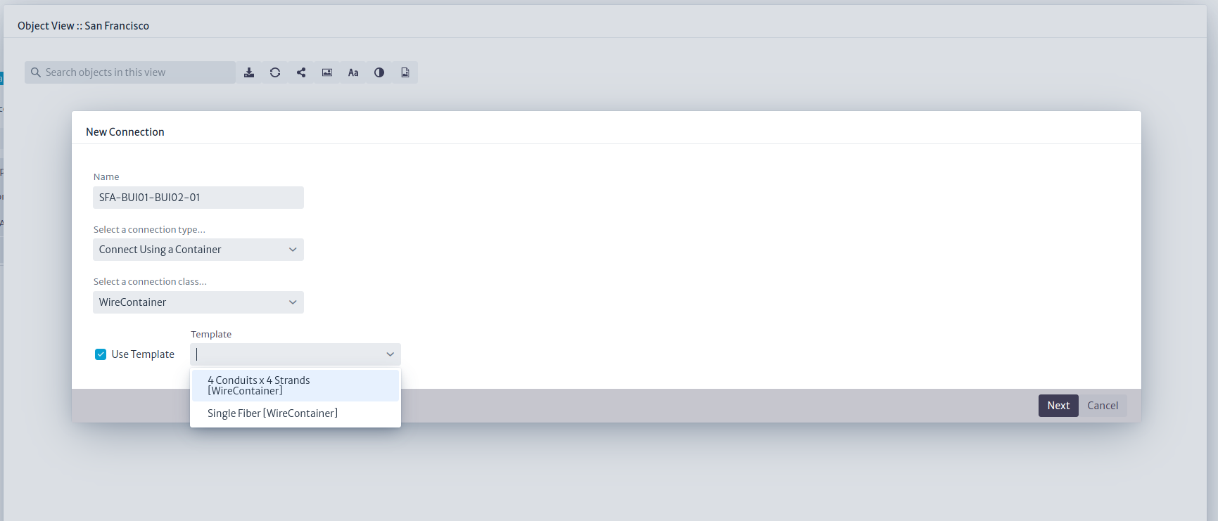
That will launch a quick wizard where you can name the connection, select its type, and optionally, choose a template as shown in the picture below.
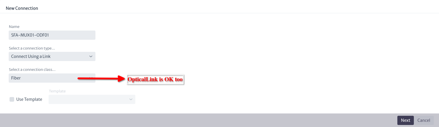
Note: The screenshot says
Fiber, but that was just the display name ofOpticalLinkin the database used for these examples.
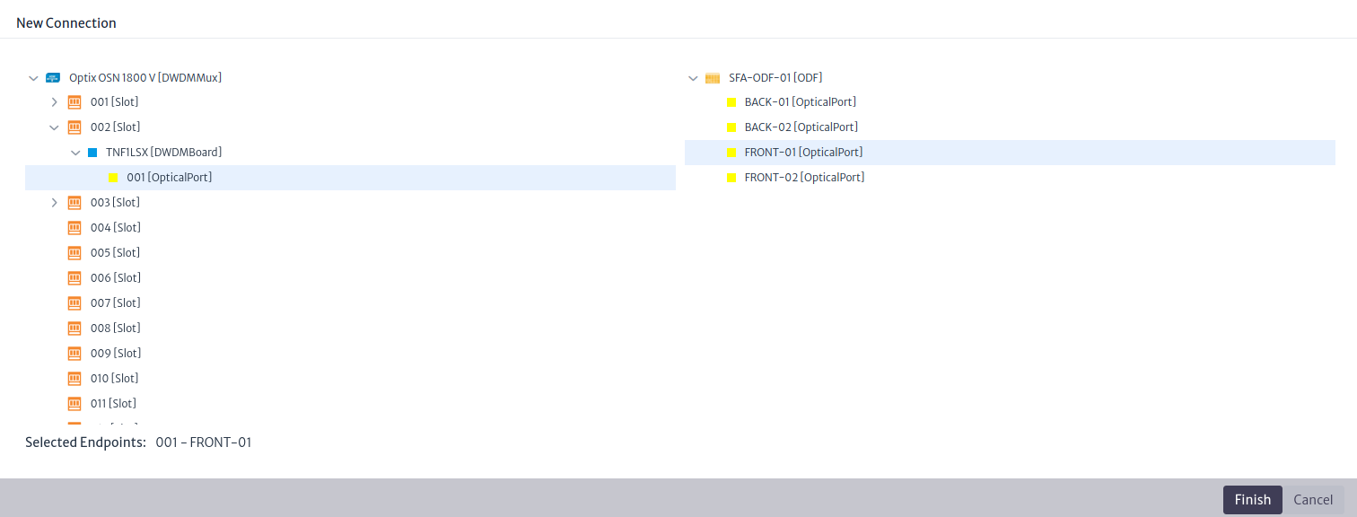
In the final steps, choose the ports
That's it. If you see a yellow line between the ODF and the multiplexer, you did it correctly (the connection color is customizable. It's the color assigned to the class OpticalLink in the Data Model Manager). Now we can launch a Physical Path, which is a view that shows the physical continuity from a given port. Select the port in the multiplexer you chose to connect and click on Physical Path in the Views section.
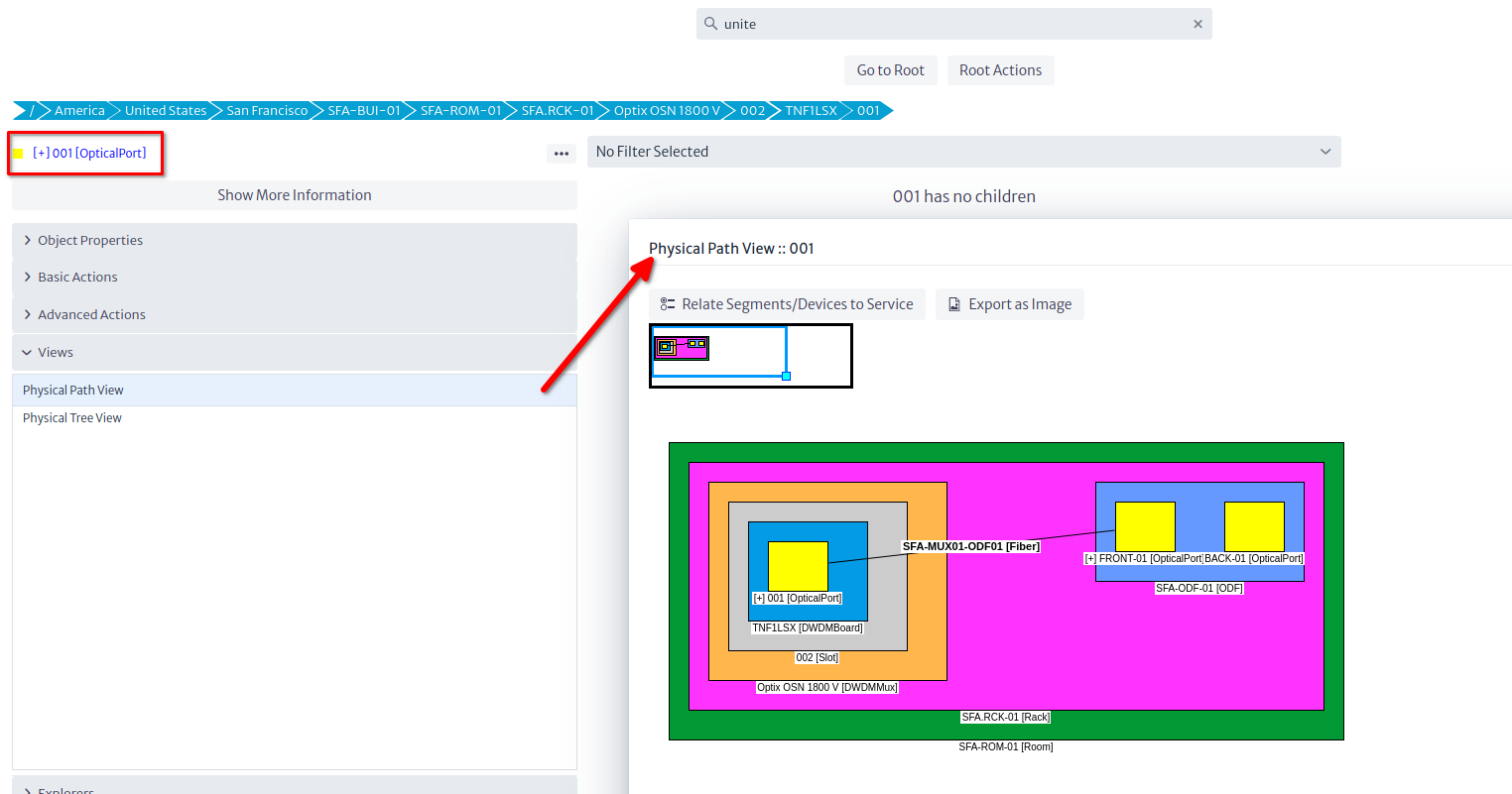
Note: The port appears blue, with a
[+]in its name. That can be done with Validators. Validators are customizable pieces of logic that check for a condition you code, and can influence the way inventory objects are displayed in the GUI. You can do some pretty neat things with them, but that will be discussed in another tutorial. The sample database has a few validators in it. The empty database has none.
Summary
So far, we have created a single site with a DWDM multiplexer and an ODF, and connected them using an
OpticalLink(fiber) by opening the parent rack's Object View and using the physical connection tool. We also learned to create Templates, and the concept of mirror as a way to bridge two ports back-to-back to provide continuity to a connection. In the next section, we will clone this site two more times, rename the relevant objects, and connect all the sites using containers in order to form a ring.
Cloning the Original Site
We will use the Copy to... operation available in the Basic Actions section or the ... button next to the object we want to copy. This will open a so-called Simple Object Selector.
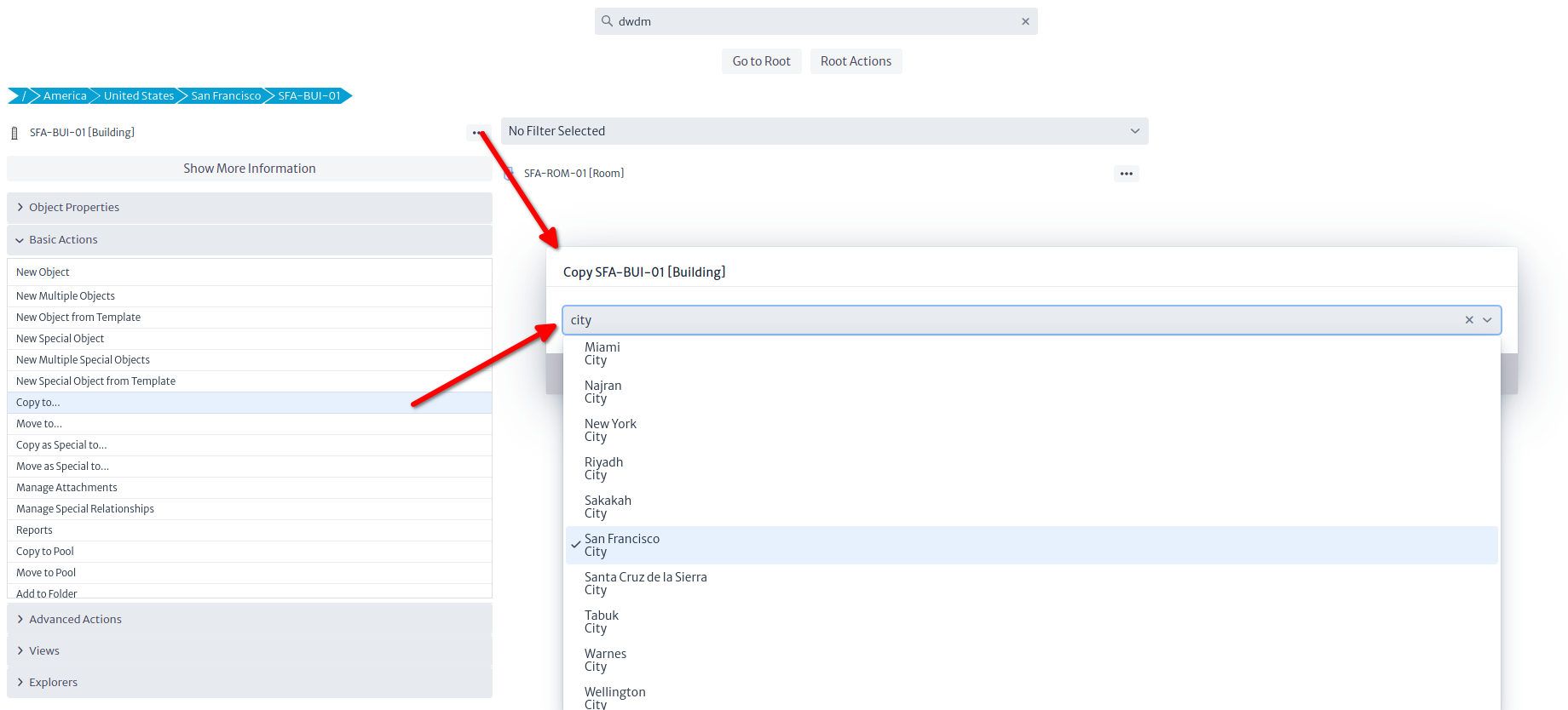
This Simple Object Selector is used in several contexts. Just type the first letters of the name of the target object or its class and pick it from the drop-down menu. In this case, we want to copy the original building inside its parent object (the city). Note that although you can pick any object in the selector, only objects allowed by the containment configuration will result in a successful copy (i.e. if you try to copy the Building to, say, a Router, an error message will be displayed). After renaming the relevant objects (building, rack, mux and ODF at least), you should end up with three sites as depicted in the picture below.
Tip: You can rename an object using the property sheet by double clicking the field name or pressing
F2.
Connecting the Sites
Using the Object View
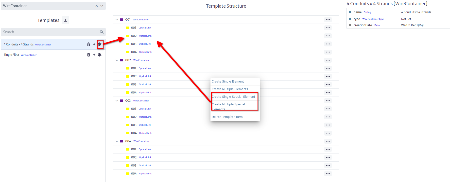
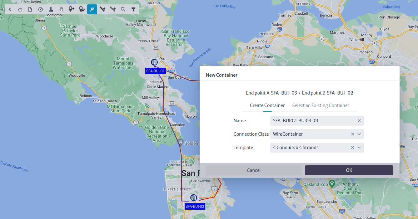
Once the nodes have been copied, we are going to connect them. Open the Object View as instructed in picture above. We will now connect building SFA-BUI-01 to SFA-BUI-02 like we did in the past section, but in this case, we are going to use a Container (that is, a conduit) instead of a Link. We will use a WireContainer (WireContainers are used to contain copper-based and optical connections, whereas WirelessLinks are used to contain wireless links (technically known as RadioLinks). You can create your own types of containers -though in most occasions this is not necessary- by subclassing GenericPhysicalContainer in the Data Model Manager). Containers and Links, like any other class in Kuwaiba, can have templates. In the sample database you will find two templates for WireContainer: One is a conduit that has 4 other smaller conduits inside, each of them with 4 fibers. The other is a cable with a single strand (might be a drop cable). You can create your own templates with real-life conduits (for example with 96+ fibers inside), just take into account that the physical connections model requires that everything inside a container is a so-called special child. We won't go into details here because this is a separate topic, just make sure you use the options indicated in the picture below.
Connecting two buildings will bring up a familiar wizard, but this time, we'll be using a WireContainer and the template with sub-containers.
In the next step we select the two buildings
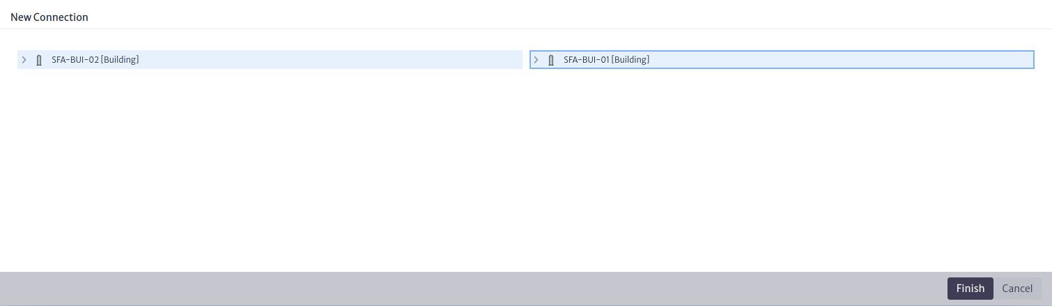
Repeat the procedure between SFA-BUI-01 and SFA-BUI-03, but NOT between SFA-BUI-02 and SFA-BUI-03. For these we'll use another way. If we followed the steps, the city's Object View should look like in the picture below. In case you are wondering, we will connect the fibers last.
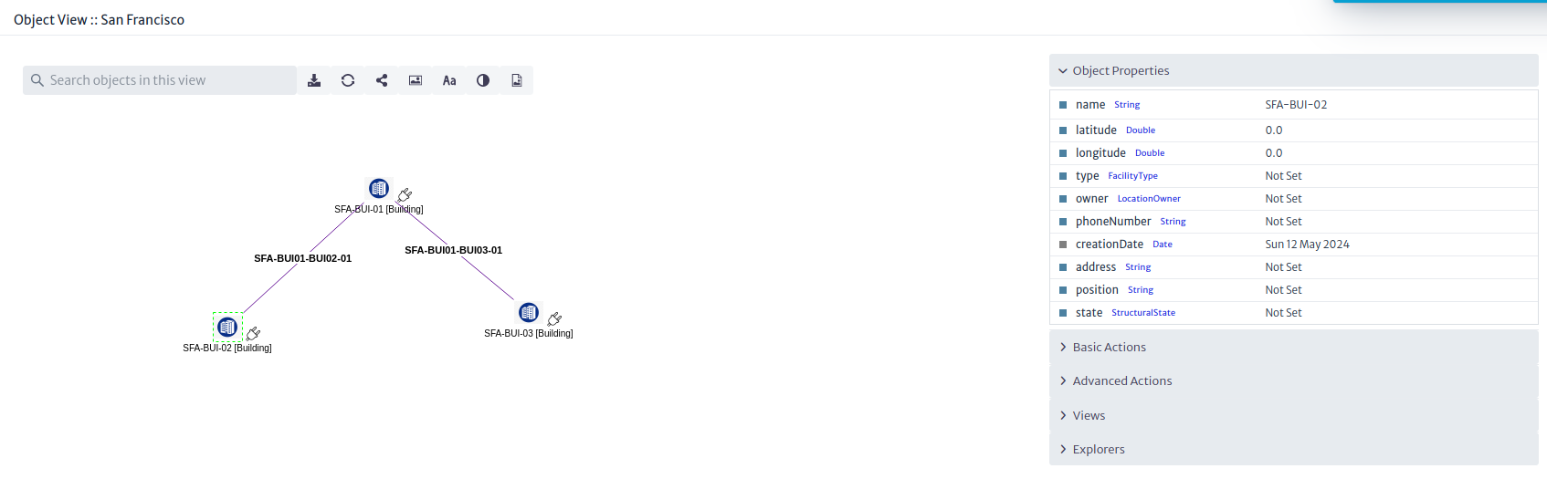
Note: This time the connections are purple, not yellow. Again, this color correspond to the color of the class (
WireContainerorOpticalLink).
Using the OSP Module
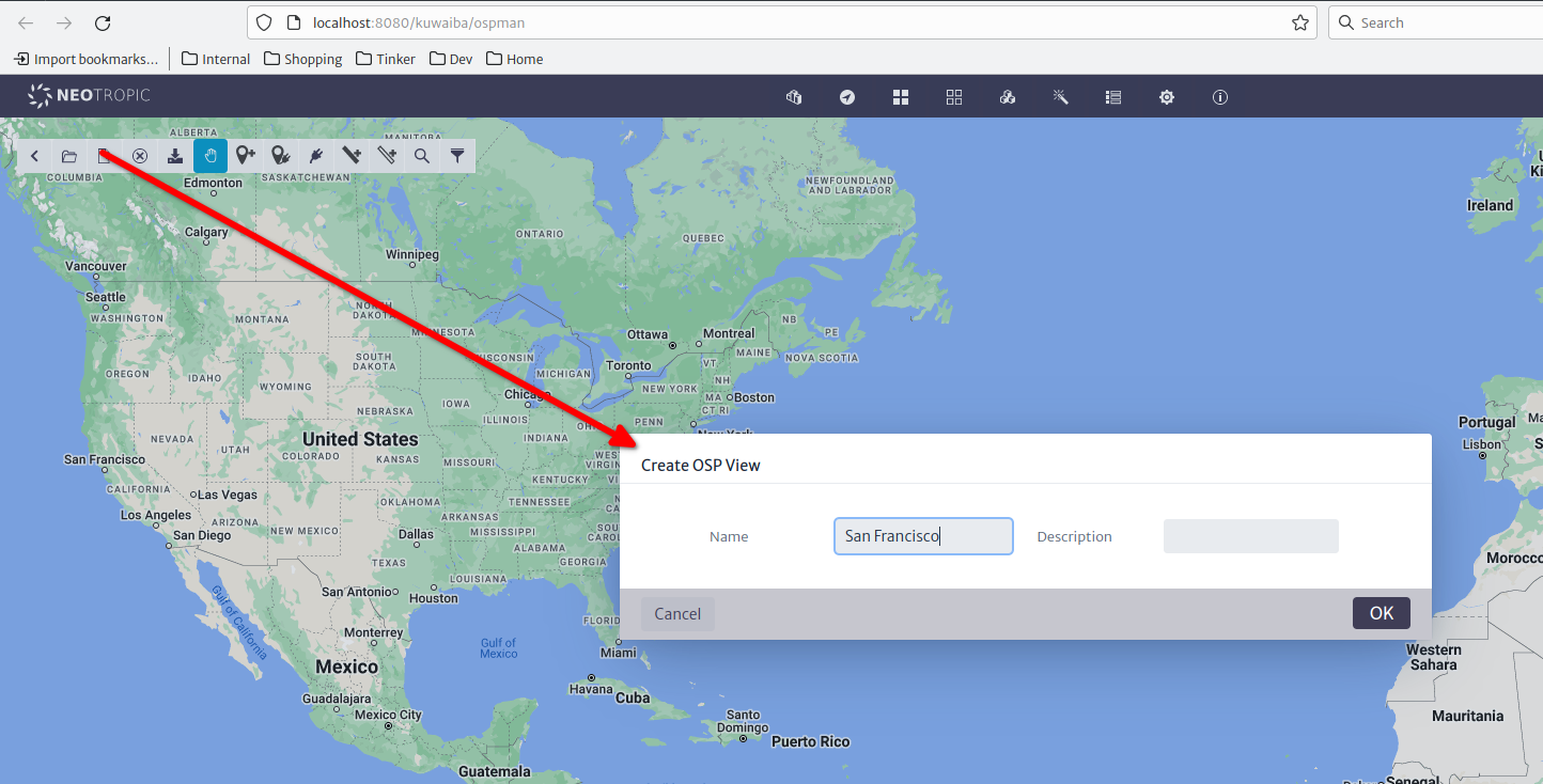
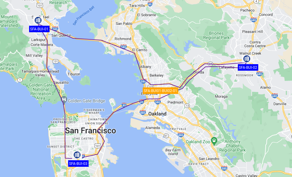
For the third arm we could do it the same way, but instead of that, we are going to use the Outside Plant Manager. This module adds a spatial dimension to the inventory. First, we are going to create a new OSP View, and name it and center the map in San Francisco.
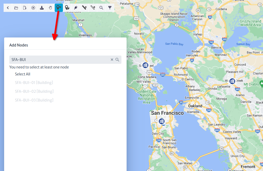
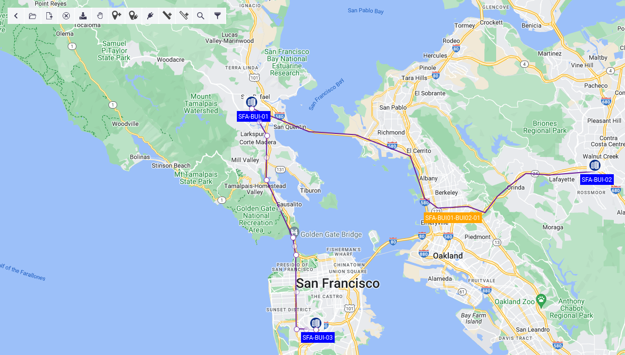
The default map provider is OpenStreeMap, but we'll be using Google Maps in the following screenshots. The behavior is the same for the sake of this example. Click the Add Node button, and in the filter text field, type SFA-BUI and hit Enter. If you followed the naming conventions, you should see the three buildings we created previously.
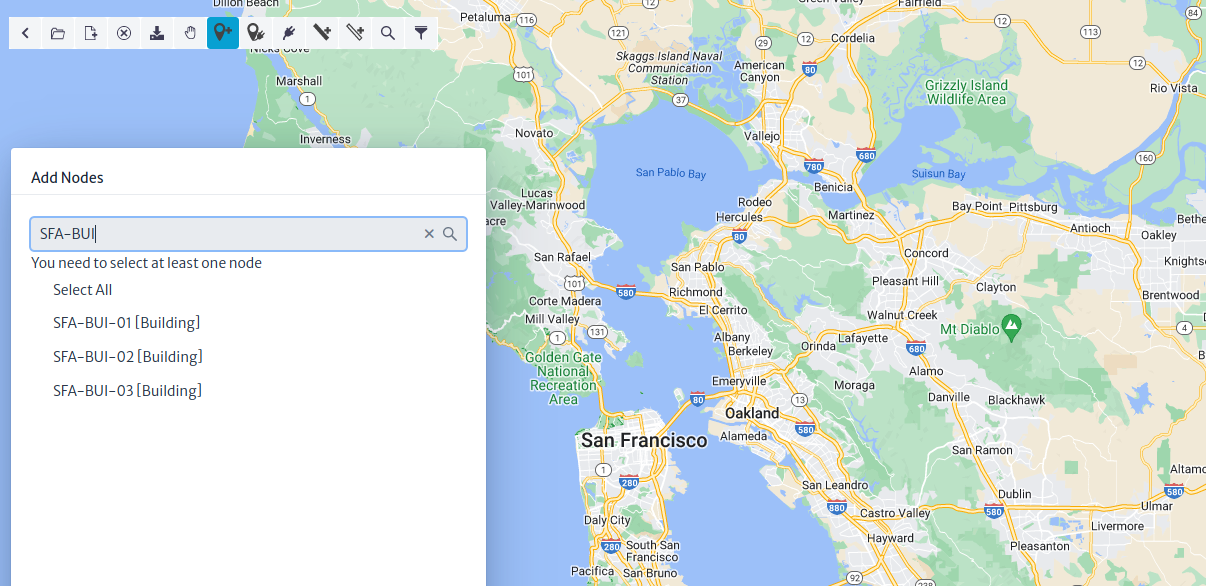
After selecting the nodes to be added, you will notice that the mouse pointer becomes a crosshair. If the building had geo-coordinates set previously, the system will ask you if you wish to override them or use them. Since we haven't set them yet, the nodes will be placed one after the other in the position you indicate.
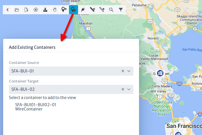
Now let's import the existing connections, and for this, use the button to the right of Add Nodes. In the form, select the endpoints of the connections you want to import. The system will detect the existing containers between the nodes.
Important
An OSP view can only contain nodes that are objects of subclasses of
GenericLocation, such asBuildings,Manholes,Poles,Housesand connections that are subclasses of GenericPhysicalContainer, such asWireContainerorWirelessContainer.
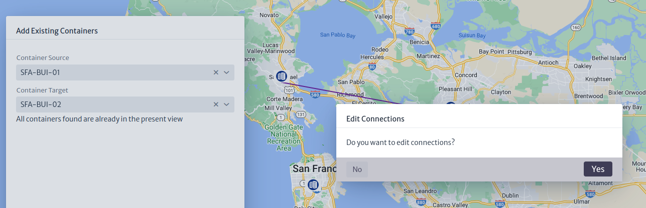
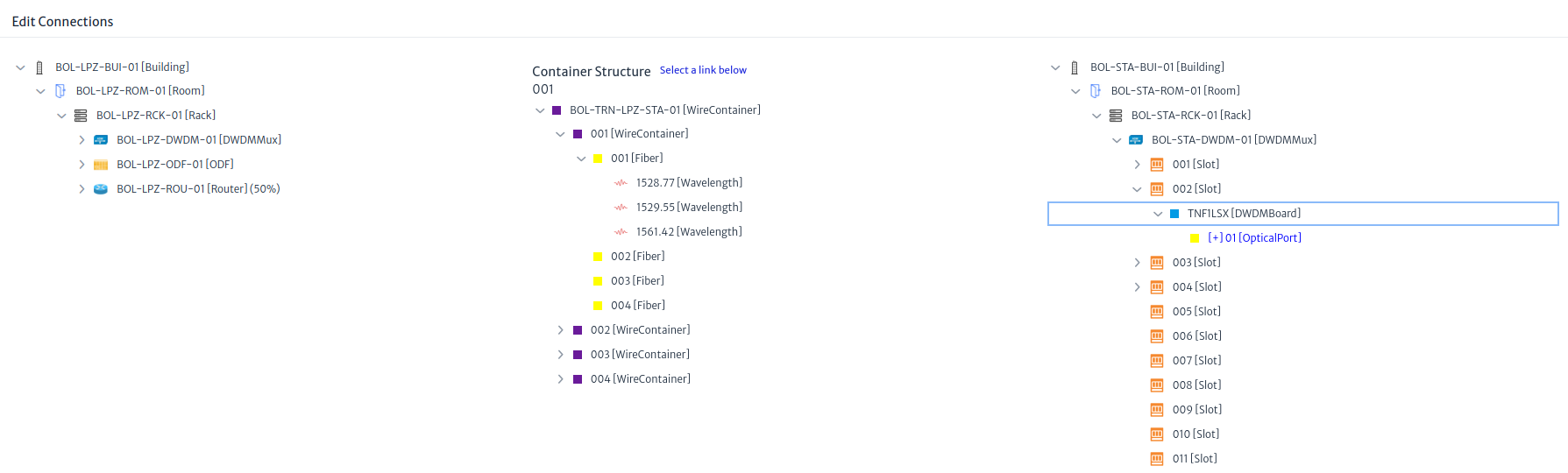
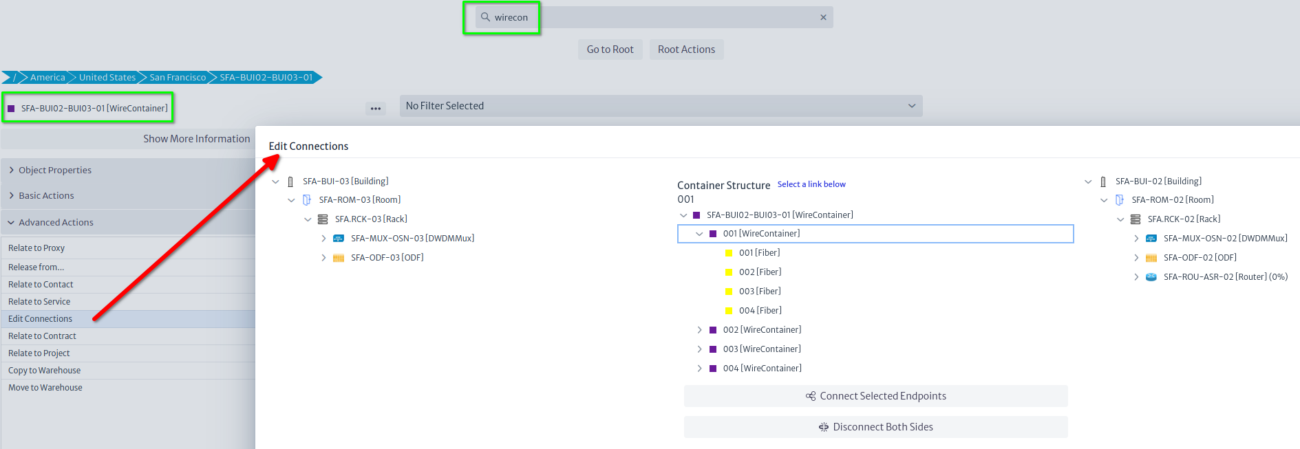
If you click the container, it will be added automatically, and you will be asked if you want to connect the fibers inside (Edit Connections, in fact) as can be seen in the picture below.
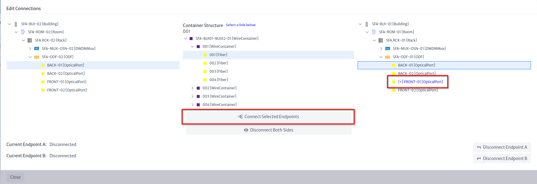
We want to connect the back ports of the ODFs on each side using the first fiber of the first subconduit. On the SFA-BUI-01 side, you will notice that the front port is already connected, since we connected the devices to the corresponding front ports. You don't have to connect both sides, but we'll do it in this example
Note
If it's relevant for your application, you can also create the lambdas under the
OpticalLinks(as Special Children) and later relate them to services or logical resources like virtual circuits. They are not to be connected, as they are not either Links or Containers, they act like channels that use the physical medium.
With the Selection Tool (the button with the hand icon), you can select the container and change its route. Do the same with the container connecting SFA-BUI-03.
There are several Configuration Variables that govern label colors and zoom levels at which labels are visible. Finally, we are going to create the final arm of the ring between SFA-BUI-02 and SFA-BUI-03. To do this, we will select the Connection Tool, then select the source building and trace the route in the map until we reach the target node.
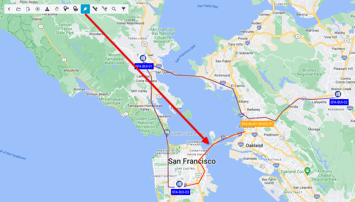
Clicking the target node will launch a similar wizard to the one we saw before, and by the end you will be offered to connect the fiber inside.
You can edit the connections of a given container at any moment by right-clicking it and selecting the option in the context menu. You can also launch the wizard from the Advanced Actions menu in the Navigation module, using the Edit Connections action.
In the end, the ring should look like this:
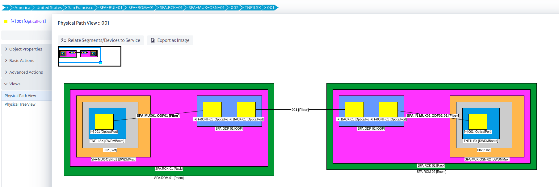
Finally, if you launch a Physical Path from the port of the first communication board of any multiplexer, you should be able to see how it reaches the next multiplexer through the ODFs on both sites and the fiber you selected in the Edit Connections action.
Getting Started with Kuwaiba
This is a very basic tutorial. When you are faced with a new tool, perhaps the most direct way to understand how it works is by getting hands-on and creating something. This tutorial will help you model a basic short messaging system using Kuwaiba.
However, I recommend doing some preliminary work to ensure that your idea is effectively translated into the tool. The first thing we will do is list the key elements of your model. In my case, I will work on a classic VAS (Value-Added Service) system: a short messaging system connected to the core network via SIGTRAN and to the BSS (Business Support Systems) via APIs. I have chosen this system because it represents the basic functionality of many value-added services and other telematics-oriented services.
Components
Servers
Physical Equipment: These will host the services.
Services
We will create four services:
- Short Message Center (SMC): Responsible for receiving, processing, routing, and storing text messages in memory for the cellular network (SMS messages of 160 characters as per the SMPP 3.4 protocol).
- Billing Server: Responsible for generating Call Detail Records (CDRs).
- Reporting Server: Handles the creation of various reports.
- Core Network Communication Server: This service manages the relationship with a Signaling Transfer Point (STP) in the core network using the SIGTRAN protocol to handle communication within a 3G/4G/5G network.
Additional Equipment
To make this work, we will need other equipment such as databases, networking gear, fiber optics, and UTP cables.
Now, let's create a diagram that relates these elements. This will help us improve our model and possibly include elements that were not initially present but are necessary (such as a rack, a datacenter, or perhaps electrical equipment). This can take you to the level of detail you want, but for now, it will be something basic.
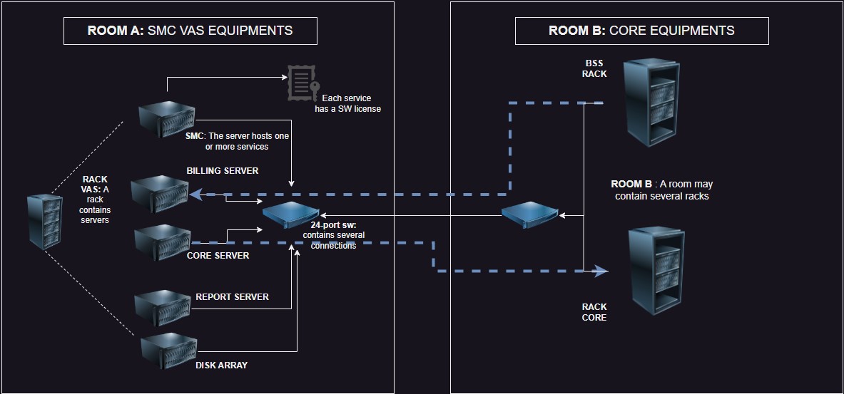 |
|---|
| Figure 1: Basic Diagram of Components |
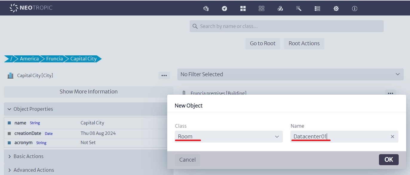
Now we are going to start transferring this graphical model to Kuwaiba. As a first step, we will locate our racks (A-B) inside a room located in a building (Datacenter A) in an imaginary city called Fruncia.
To do this, we will use the "navigation" module:
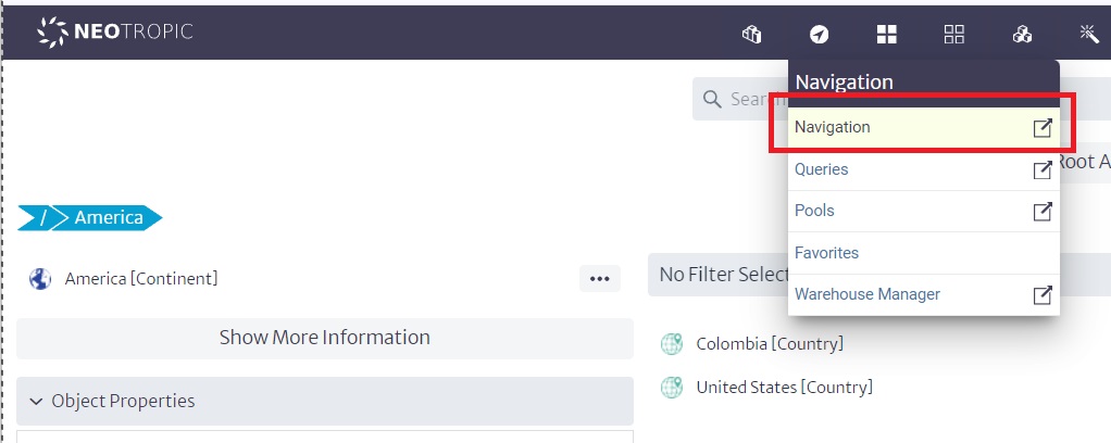 |
|---|
| Figure 2: Navigation Module |
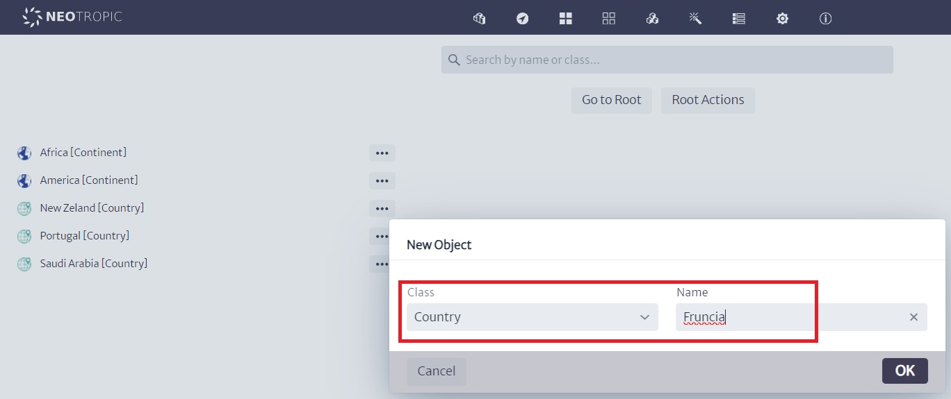
Let’s start from the root by clicking on "Go to root", which will display some "countries" or "continents" that were created earlier. At this point, we could create an imaginary continent or include Europe or any starting point by clicking on "root actions/new Object".
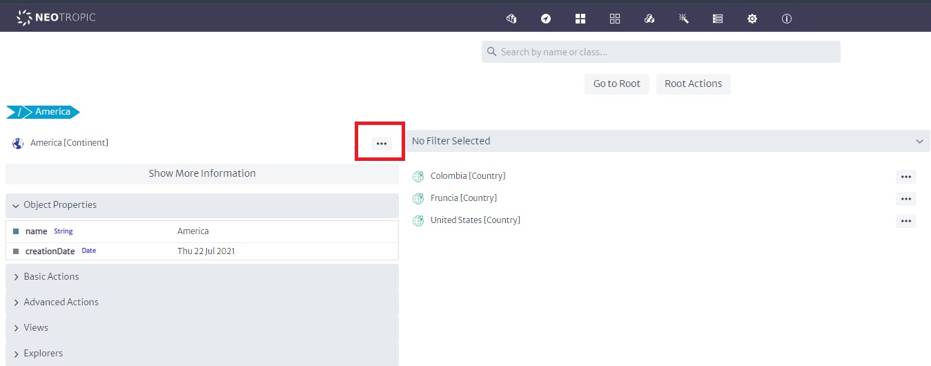
In our case, we will create Fruncia within America. So, we will click on America:
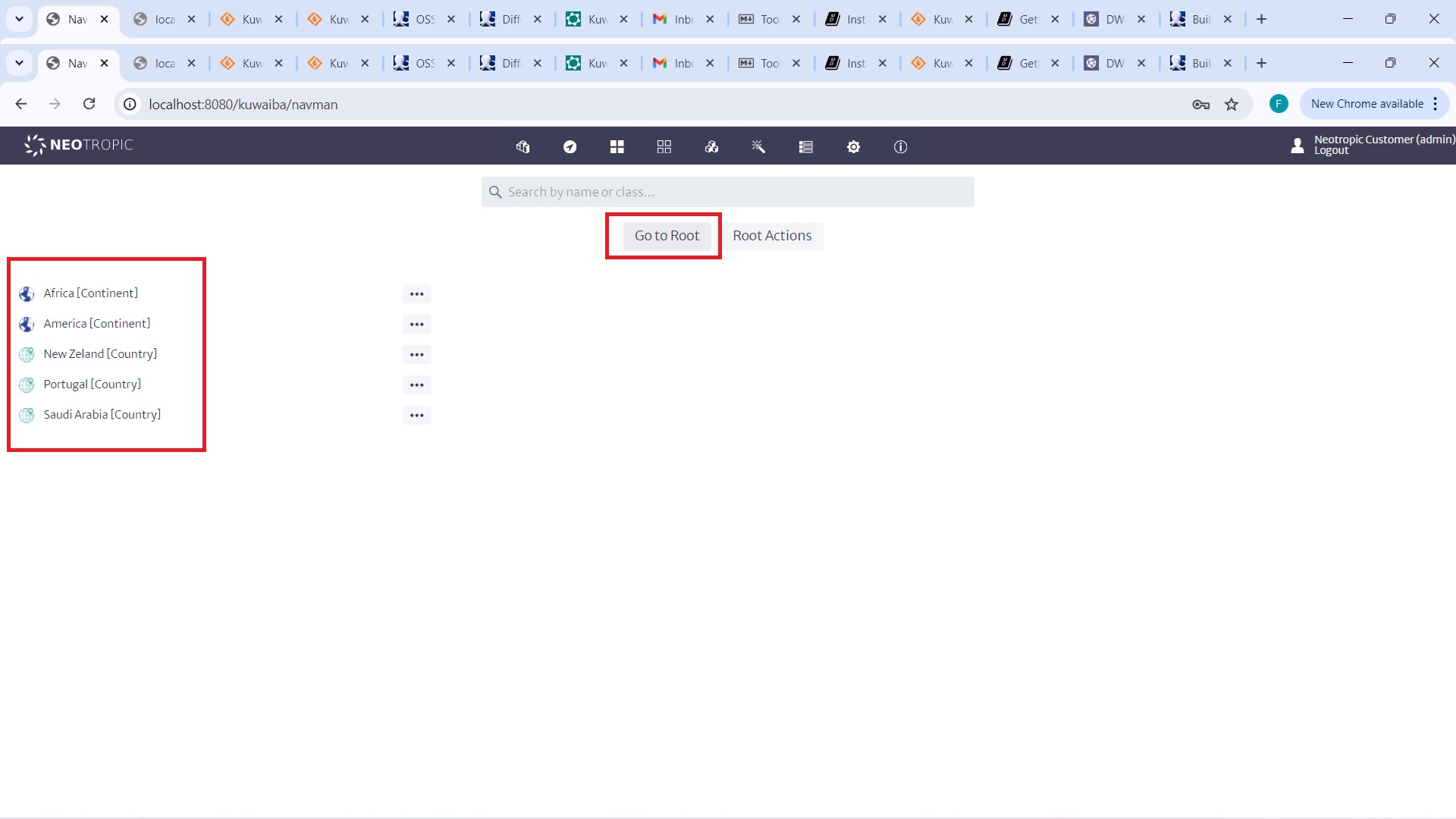 |
|---|
| Figure 3: Navigation from Root to America |
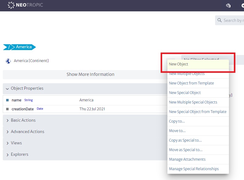
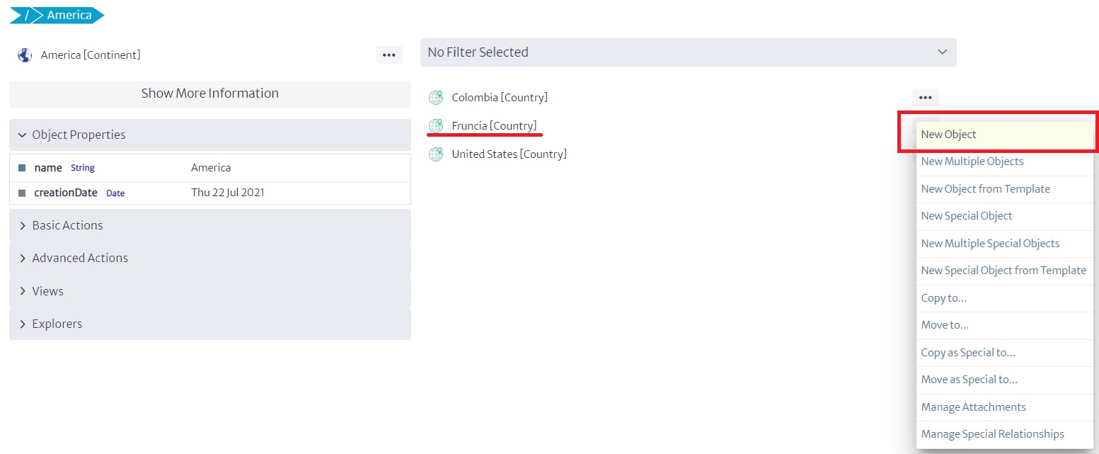
Then, we will click on the three dots in front of America and create a new object called Fruncia.
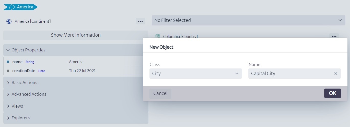
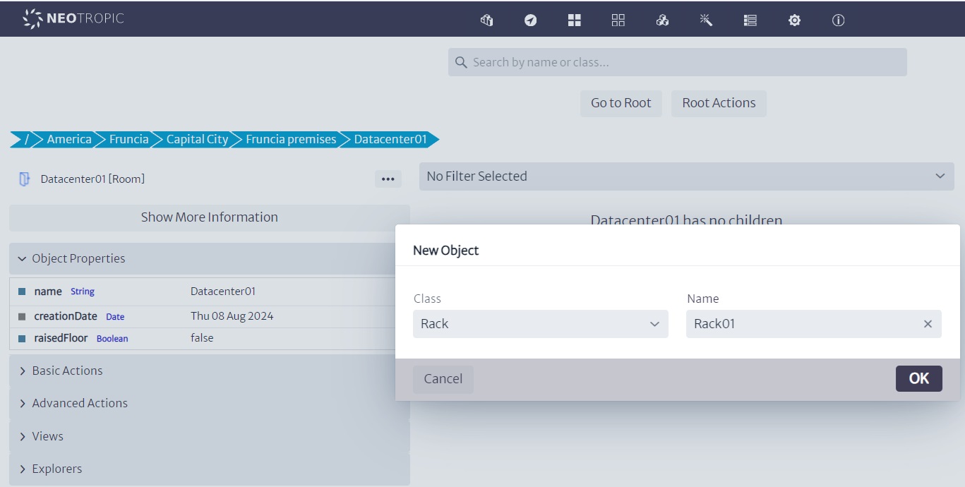
Next, we will look for the three dots for the Fruncia object. A dialog will appear asking what kind of class we will create. We will choose the appropriate type for each case, such as a country. We will do the same by creating a building and then a datacenter:
 |
|---|
| Figure 4: Creating Objects of Class |
This means we are creating a structure where a continent contains a country, that country contains cities and buildings, and those buildings contain datacenters.
Of course, I skipped many details (remember that this is a basic tutorial), but we could have a very detailed structure, with all kinds of details... region, district, neighborhood, floor, etc.
 |
|---|
| Figure 5: Navigation While Creating Objects |
 |
|---|
| Figure 6: Creating More Objects |
 |
|---|
| Figure 7: More Objects Created |
 |
|---|
| Figure 8: Continuing to Create Objects |
 |
|---|
| Figure 9: Additional Object Creation |
I created several racks, thinking of a real example of a similar distribution, where in a single datacenter there were core equipment, networking equipment, VAS equipment, and OSS/BSS, all on different rows of racks, connected by 24-port L2 switches. In this case, we will have one rack with three servers connected to a switch, which is then connected to another switch in a different rack where the BSS and Core racks are located.
 |
|---|
| Figure 10: Racks in Datacenter01 |
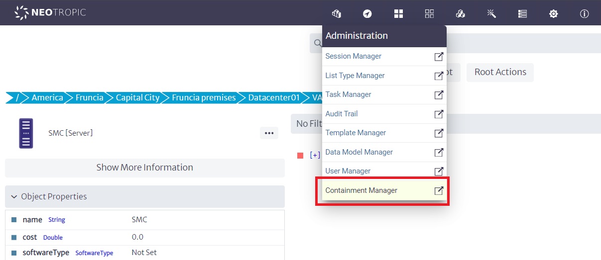
Now, what we are going to do is place the servers in each of the racks. However, we need to take a preliminary step because the servers in the tool, by default, may contain optical ports, and I require that my design includes electrical ports. Therefore, I need to use the Containment Manager to modify the containment hierarchy of the servers.
 |
|---|
| Figure 11: Containment Manager Interface |
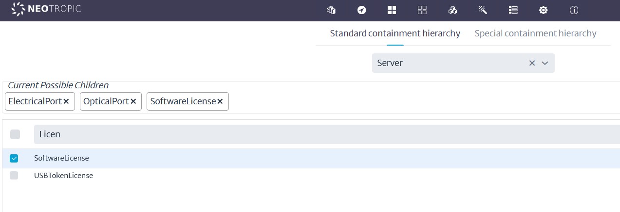
To do this, I will search for the Server class and, using the search function, I will add electrical ports as children, as shown in the following image:
 |
|---|
| Figure 12: Adding Electrical Ports to Server Class |
Introduction to 5G Modeling in Kuwaiba: Application in IoT and Mobile Internet
This manual is designed for anyone interested in modeling 5G networks and IoT applications using the Kuwaiba tool. This model is one of many possible versions and does not aim to be a definitive recipe, as Kuwaiba allows for a multitude of different approaches.
The objective is to provide a step-by-step guide on how to structure and manage the network resources (RFS) that support customer-facing services (CFS), in these cases, the operation of smart traffic lights and the provision of mobile internet connectivity over a 5G network. This approach not only helps visualize the network topology but also understand how different components interact to ensure efficient and reliable services.
Throughout the manual, we will explore how Kuwaiba facilitates the configuration and modeling of these elements, allowing telecommunications companies to leverage the advanced capabilities of 5G to enable IoT and mobile internet applications with precision and flexibility.
Table of Contents
- 1. Introduction to 5G Modeling in Kuwaiba: Application in IoT and Mobile Internet
- 2. DATA MODEL
1. Required RFS for 5G Smart Traffic Lights and Mobile Internet Service
To model smart traffic lights and mobile internet services on a 5G network using the RFS (Resource Facing Service) concept, we need to understand the physical and virtual elements that make these services possible. These include the connectivity infrastructure, processing units, and platforms that support the operation of IoT devices (smart traffic lights) and mobile services.
Below, we'll dive into each module and explain how it contributes to the overall architecture of 5G IoT services.
1.1 Network Connectivity
Network Connectivity is the backbone of the 5G system, ensuring data is transmitted efficiently between devices, sensors, and the central network. The two key components here are Radio Access Network (RAN) and Backhaul:
1.2 Radio Access Network (RAN)
- What it is: The RAN is the part of a mobile network that connects user devices, like smartphones or IoT devices (e.g., smart traffic lights), to the core network. It includes key elements such as antennas, Remote Radio Units (RRUs), and Distributed Units (DUs).
- For smart traffic lights: RAN provides wireless connectivity between the traffic lights and the 5G network.
- For mobile internet: RRUs and antennas allow mobile devices (smartphones, tablets) to connect to the network, supporting high-speed data transmission.
1.3 Fronthaul
- What it is: The fronthaul connects the Radio Unit (RU) to the Distributed Unit (DU) in the 5G RAN, facilitating the communication between antennas and the rest of the network.
- Importance: Ensures low-latency communication between the antennas and the core network for both smart traffic lights and mobile users.
1.4 Network Backhaul
- What it is: Backhaul is the infrastructure that links the RAN (base stations) to the core network. Typically, it uses fiber optic or microwave links to carry data.
- For both services: Backhaul is crucial for transporting data from smart traffic lights and mobile devices to the network core, where the data is processed or forwarded to the internet.
1.5 Edge Computing
Edge Computing brings computation closer to the location where it's needed, reducing latency by processing data near the devices (IoT or mobile). This is essential for real-time operations like traffic control or high-speed internet delivery.
Edge Computing Nodes
- What they are: These are localized processing units that perform computations near the IoT devices or mobile users, reducing the need to send data to centralized servers.
- For smart traffic lights: The edge nodes process traffic data locally, enabling real-time decisions for controlling traffic flow (e.g., changing light timings based on vehicle flow).
- For mobile internet: Edge nodes improve the speed of data delivery for mobile users by caching content locally and reducing the load on the central network.
1.6 5G Core Network
The 5G Core Network is responsible for routing, managing sessions, and controlling user mobility. This section includes the critical network functions that manage IoT and mobile services.
User Plane Function (UPF)
- What it is: The UPF is responsible for routing and forwarding user data traffic.
- For smart traffic lights: It routes IoT traffic between the smart traffic lights and control systems.
- For mobile internet: It handles high-volume user data and ensures proper routing to external networks (e.g., the internet).
Session Management Function (SMF)
- What it is: The SMF manages sessions and tunnels, establishing, modifying, and terminating network connections.
- For smart traffic lights: It manages stable connections between the traffic lights and central control systems.
- For mobile internet: It ensures proper Quality of Service (QoS) by managing the sessions of millions of mobile devices.
Access and Mobility Management Function (AMF)
- What it is: The AMF manages access and mobility, ensuring seamless connection and authentication for devices.
- For smart traffic lights: It handles mobility for IoT devices (smart traffic lights), allowing continuous connectivity.
- For mobile internet: It manages mobile user handovers between different cells, ensuring uninterrupted service for users on the move.
1.7 Network Slicing
Network Slicing is a feature of 5G that allows the network to be partitioned into multiple virtual networks (or slices) to meet specific service requirements, such as low-latency for IoT or high throughput for mobile data.
Dedicated Network Slice for IoT (Smart Traffic Lights)
- What it is: A network slice configured to support the low-latency, high-reliability demands of smart traffic lights.
- Why it's needed: Ensures that traffic control systems can operate without delays, preventing accidents or traffic jams.
Dedicated Network Slice for Mobile Internet
- What it is: A slice designed to handle large data volumes for mobile users, ensuring fast internet access.
- Why it's needed: Provides high bandwidth and efficient allocation of resources for mobile internet users.
1.8 IoT Platforms
IoT Device Management Platform
- What it is: A platform that manages IoT devices (e.g., smart traffic lights), providing real-time monitoring and firmware updates.
- For smart traffic lights: This platform allows operators to configure and manage the operational parameters of the traffic lights remotely, ensuring optimal performance.
Mobile Device Management Platform
- What it is: This platform manages mobile devices, ensuring secure access, authentication, and device enrollment.
- For mobile internet: It provides mobile operators with control over user devices, enhancing security and device tracking.
1.9 Security Infrastructure
Virtual Firewalls
- What they are: Firewalls that secure communication between IoT devices (smart traffic lights) and control systems or between mobile devices and the core network.
- For smart traffic lights: Protects sensitive data from unauthorized access or cyber-attacks.
- For mobile internet: Ensures the security of user data and protects the core network from external threats.
Authentication and Authorization Functions
- What they are: These functions ensure that only authorized devices can access the network.
- For both services: Guarantees that only trusted IoT or mobile devices can connect to the network, preventing unauthorized usage.
1.10 Sensor Networks and Data Feeds
IoT Sensorssudo
- What they are: Sensors that collect data from the environment, such as traffic flow or pedestrian activity, and feed this data to the network.
- For smart traffic lights: These sensors gather real-time information about traffic, which is used to adjust traffic light timings dynamically.
Mobile Device Location and Data Feeds
- What it is: Location data from mobile devices that help optimize network coverage or provide location-based services.
- For mobile internet: This data helps the network optimize coverage and offer services tailored to a user’s location.
2. DATA MODEL
The Data Model Manager will be used to create all the necessary objets for the model. For an overview of what will be generated, see Figure 1
Figure 1: High Level Diagram

Next, we will create all the necessary objects according to the proposed diagram.
2.1 RAN
- RRU (Remote Radio Unit), which will be connected via fiber optic.
- We also need poles, towers, or indoor/outdoor assembly kits for installation and infrastructure support. ## No differentiation will be made between the 5G antennas of Zones 1 and 2, but the connected devices (which must be added) will change, including cameras, smart traffic lights, indoor antennas, and embedded systems with sensors.
Figure 2: RAN Objets


2.2 Edge Computing / 5GCN / IMS /RIC
In 5G, the approach shifts away from proprietary hardware with specialized interfaces. Instead, we leverage powerful servers that host virtualized network functions (VNFs) or Network Functions Virtualization Infrastructure (NFVI). These VNFs are modular software components designed to perform specific, specialized functions within the network.
This new architecture enables greater flexibility and scalability, as the same physical infrastructure can support multiple functions through software rather than relying on dedicated hardware for each task. For our model, we will define several classes that will be used across different modules, each representing distinct software components or functions.
By using virtualized resources, we achieve a more efficient and adaptable network architecture, allowing us to quickly implement, manage, and scale network services as needed, without the limitations of traditional hardware-based solutions.
Location or Facility
- Container: Could be a physical room, micro data center, or enclosed cabinet. It could even be housed in an outdoor environment, depending on how distributed the Edge is intended to be.
- Rooms or datacenters
Servers
- General-purpose compute servers: These will process local data.
- Storage arrays: These could include high-performance SSDs to store relevant data closer to the source.
Figure 3: Edge Computing 1.


IOT devices
- Cameras-5GRouters-Smart traffic lights
Figure 4: IOT Devices.

2.3 Applications
Edge apps:
- V2X applications (Vehicle-to-Everything): These would include software systems to manage vehicle communication with infrastructure, such as traffic lights.
- Real-time analytics: Applications that process IoT data from sensors, traffic cameras, and other devices at the Edge, enabling immediate decision-making.
- DU software (Distributed Unit software): Handles functions related to the 5G network (e.g., signal processing, radio link management).
- MEC (Multi-access Edge Computing) software: A key part of many 5G deployments, it enables low-latency services and optimizes data processing at the Edge.
- AI/ML inference engines: For real-time decision-making, particularly if traffic monitoring and adaptive responses are a core part of the system.
5GCN (5G Core Network) apps:
- User Plane Function (UPF): Routing and forwarding of user data traffic.
- Session Management Function (SMF): Management of sessions and network tunnels.
- Access and Mobility Management Function (AMF): Management of device access and mobility.
- Policy Control Function (PCF): Application and control of quality of service (QoS) policies.
- Authentication Server Function (AUSF): Authentication of devices and users.
- Unified Data Management (UDM): Management of subscription data and user profiles.
- Network Repository Function (NRF): Registration of available network functions.
- Network Slice Selection Function (NSSF): Selection and management of network slices.
IMS (IP Multimedia Subsystem) apps:
- Call Session Control Function (CSCF): Control of multimedia sessions (voice, video, messaging).
- Multimedia Resource Function (MRF): Management of multimedia resources and voice/video mixing.
- Home Subscriber Server (HSS): Management of subscriber information.
- Media Gateway (MGW): Gateway for voice and multimedia traffic between IP and circuit networks.
- Breakout Gateway Control Function (BGCF): Selection of network gateway for outgoing calls.
RIC (RAN Intelligent Controller) apps:
- Near-Real Time RIC (Near-RT RIC): Near-real-time control and optimization of the RAN
The first step will be to create a list of the software products that will be used under a fictional provider called 5GInc (for detailed information on the following steps, refer to the user manual, section on lists and software manager).
Figure 5: List Type.


The license management module will now be used to create a centralized license pool for 5G software.
Figure 6: Software Manager.


Now, using the browser, ensure that the object trees are structured as follows.
RAM Zone 1:
- America
- Fruncia
- FrunciaCity
- Zone1
- Pole1 - ZoneX[Pole]
- 5GRouterStreetX + SmartTrafficLightStreetX
- Pole5
- Antenna5G
- RU
- opticalPort
- RU
- Antenna5G
- Zone1
- FrunciaCity
- Fruncia
RAM Zone 2:
- America
- Fruncia
- FrunciaCity
- Zone2
- Building
- Antenna5G
- RU
- opticalPort
- RU
- Antenna5G
- Building
- Zone2
- FrunciaCity
- Fruncia

Edge Computing
- RAM Zone 2:
- America
- Fruncia
- FrunciaCity
- EdgeDatacenter
- Floor_1
- EdgeRoom
- EdgeRack
- (Servers/opticalPort-DiskArray/OpticalPort-OpticalSwitch)
- EdgeRack
- PowerRack
- UPS
- PowerPort
- UPS
- EdgeRoom
- Floor_1
- EdgeDatacenter
- FrunciaCity
- Fruncia
- America
Figure 7: Software Manager.

Core Equipments
- America
- Fruncia
- FrunciaCity
- CoreDatacenter
- Floor_1
- CoreRoom
- CoreRack
- (Servers/opticalPort-DiskArray/OpticalPort-OpticalSwitch)
- CoreRack
- CURack
- (Servers/opticalPort-DiskArray/OpticalPort-OpticalSwitch)
- PowerRack
- UPS
- PowerPort
- UPS
- CoreRoom
- Floor_1
- CoreDatacenter
- FrunciaCity
- Fruncia
Now we will associate the licenses with the servers. To do this, use the advanced actions menu of each server object, select the %G pool created, and assign the license to each server.
Figure 8: Linking Licenses.

We can now verify the result using the explorer:
Figure 9: Explore relationships.

2.4 Connections
Through the Object View option in the Views menu, we will create the internal connections of the racks, from the servers to the switch in each rack.
Figure 10: Internal Physical Connections


We will now create wireless connections between the antennas and the traffic lights. To do this, we must ensure that ports exist at each end.
###FALTA!!!
Electrical connections should be handled in the same way, except they are connections between electrical ports. Let's, for example, connect the Edge servers to a PDU within the rack, which would then connect to the power rack, a UPS, and a primary AC power source
Figure 11: Power Connections


2.5 Slicing
In this section, our goal is to represent the interactions between different software modules. It's important to remember that 5G introduces the concept of network slicing, which enables the creation of isolated virtual networks tailored to specific service requirements. Using this concept, we aim to design flexible and efficient network architectures.
By leveraging special relationships between modules, we can define how different parts of the system interact. For example, we can model a Radio Access Network (RAN) interacting with a single Access and Mobility Management Function (AMF), which, in turn, may interact with different Session Management Function (SMF) and User Plane Function (UPF) modules, depending on the service being modeled.
This allows us to slice the network in a way that provides optimal performance and resource allocation for various use cases, such as low-latency IoT services or high-throughput mobile data.
The relationships and virtual ports created between these modules represent the flow of data and control across the network, ensuring that each slice meets its unique requirements. These interactions between modules are fundamental to the flexibility and scalability of a 5G network, enabling a range of applications from IoT to mobile internet with varying performance and reliability needs.
As a reference, we will use Figure 12.
Figure 12: Module "Connections"

Using the explorer, we can visualize the established relationships:
Figure 13: Special Relationships

Bulk Upload in Kuwaiba
Introduction
There are several scenarios when you need to automated the creation of many objects from one or multiple sources. While Neotropic SAS has a proven Migration Framework to deal with ETL requirements in big network inventory projects, here you will learn how to create simple tasks for you day-to-day data ingestion needs in Kuwaiba.
In early versions of Kuwaiba, there used to be a Bulk Upload functionality. It defined a simple format of plain text file, and each line had a syntax that told the ingestion algorithm how to process it. It was useful, but pretty limited when more complex business rules were involved, and the processing of each line was stateless, limiting its performance when some lines used information from previous ones. Other optimizations were not possible, and direct access to the database was not allowed. This feature was dropped in version 2.0.x in favor of Task Manager scripts. The main objective of the Task Manager is to provide a way to automate tasks in Kuwaiba. Tasks are Groovy/Java scripts that leverage the different integration APIs in Kuwaiba (such as the Persistence API, that abstracts the access to the database and exposes methods to manipulate the inventory objects regardless their nature) in order to perform simple or complex actions. Having the possibility to use the full power of a programming language and direct access to the database, a system administrator can create, among other things, powerful and performant routines to process and ingest data. How to code scripts and use the available APIs is outside the scope of this document, but you can find a plethora of examples in the official code repository not only of tasks, but also validators, reports and filters. The following steps will guide you through the process to use an on-boarding script to import a basic containment structure.
On-boarding Process
- Download the sample script from the repository
- Go to the Task Manager module and click on New, and paste the contents of the script in the editor. make sure you read carefully the header with additional instructions and tips.
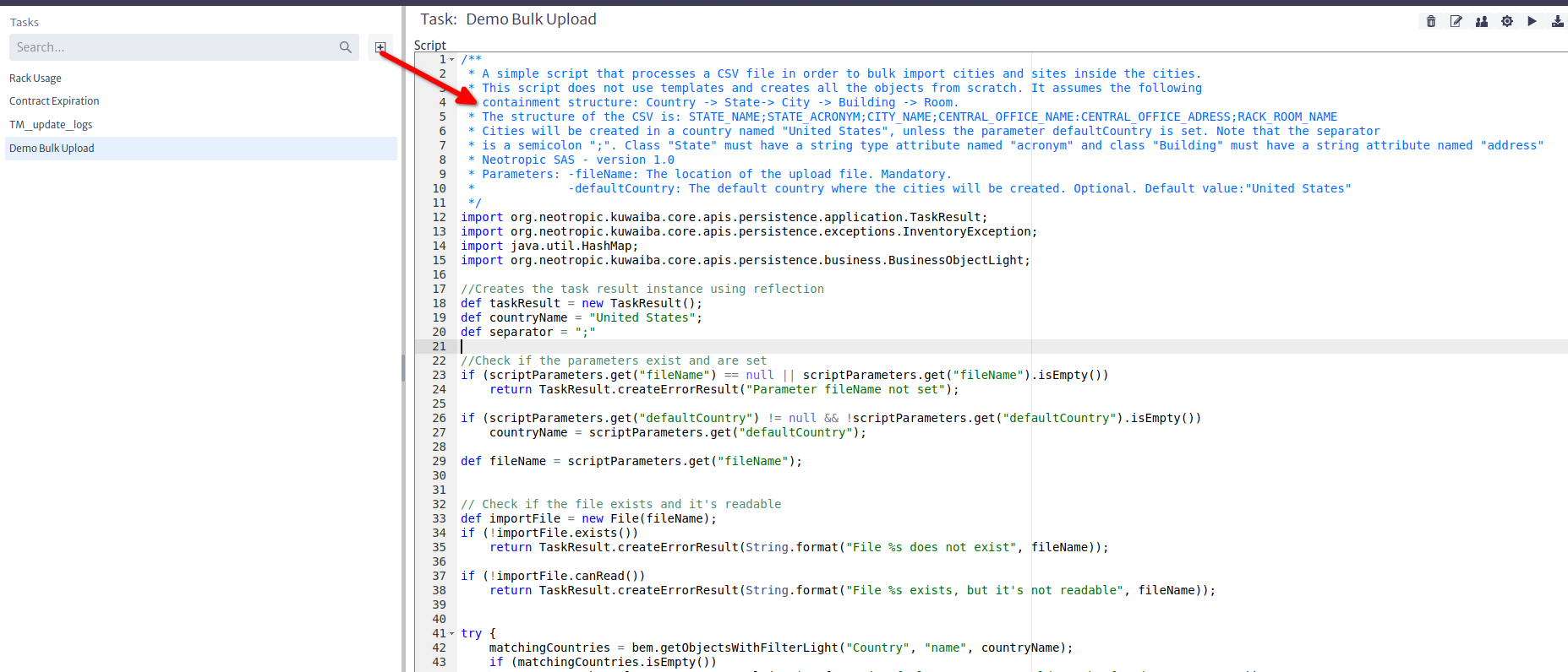
- Download the sample import file from the repository. This file contains a few lines representing Rooms inside Central Offices, inside Cities.
- Place the sample file in a location readable by the server. If you are using Docker, inside the container filesystem (volatile), or on an external mounted volume (persistent).
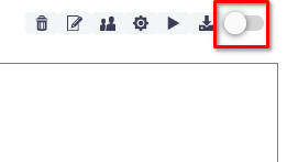
- Make sure the Commit on Execute option is unchecked. This will help you test the results before actually modifying the database. No changes will be committed until you set this option to true.
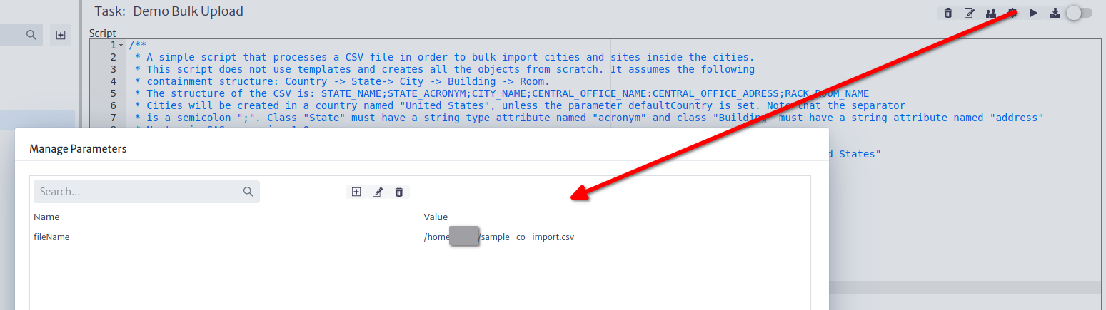
- Set the fileName task parameter to your import file location.
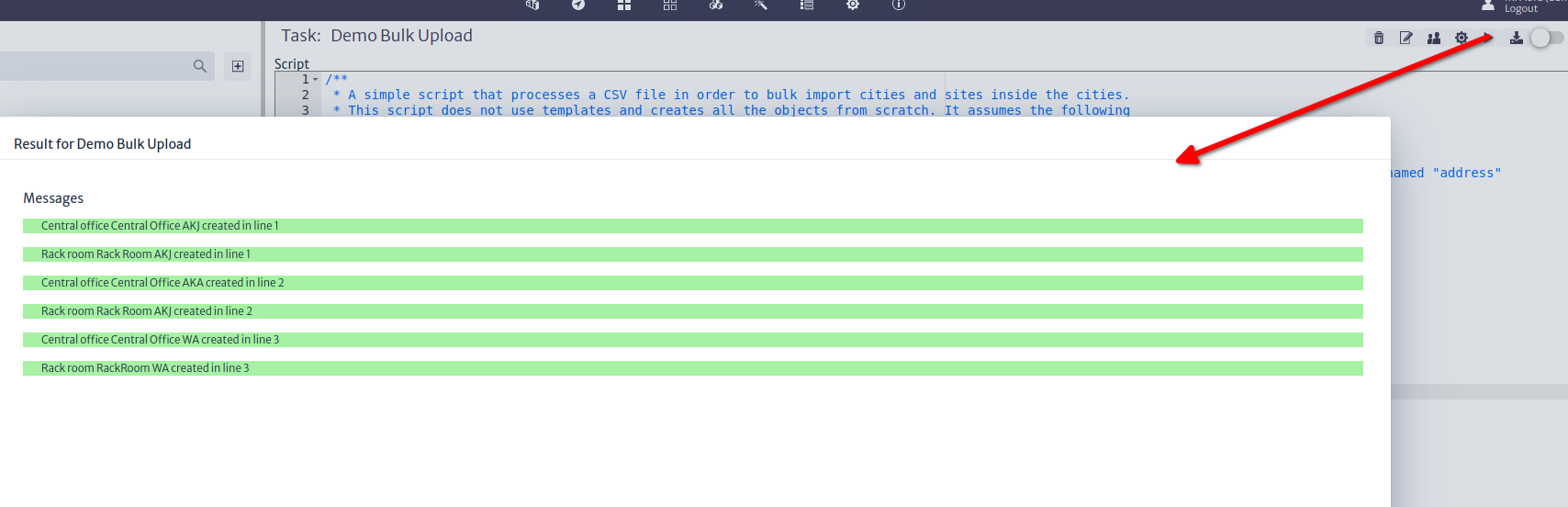
- Run the task. Running the task will save the script automatically. Once you see all messages in green, check the "Commit on Execute" and run the task again.
Further Steps
- Most import scripts look like that, plus optimization routines (caching strategies, direct access to the database, etc). Make sure you take a good look at the methods of the
BusinessEntityManager, which is part of the Persistence API, and handles most of the basic inventory object manipulation logic. His siblings MetadataEntitymanager and ApplicationEntityManager perform equally important tasks. - The repository has another example closer to a real-world scenario. This script processes the hardware export file of Huawei's U2000 DWDM NMS. Check it out, you will learn a couple of tricks from it.
- Kuwaiba 2.5's Task Manager brings important improvements in terms of API scope/structure and code management facilities. Stay tuned for further developments.
Creating a New Module
Modules in Kuwaiba help structure and organize various aspects of the system, facilitating the management of a wide range of resources and functionalities. They adapt to the changing requirements of the business and technological environment. Additionally, you can model any aspect relevant to everyday life.
Create a Module
Kuwaiba Modules
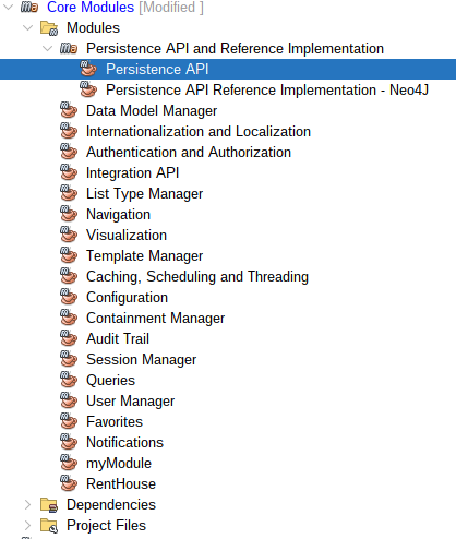
Application modules are located in the Modules folder of the main application.
Kuwaiba handles 3 types of modules:
- Core Modules: Main modules of the application.
- Optional Modules: These are additional modules specific for telecommunications management that are not essential for the basic operation of Kuwaiba. Although Kuwaiba can operate without these modules, they can be useful for users who need telecommunication-related functionalities.
- Commercial Modules: Modules designed to be licensed commercially and that will not be open source, providing functions for more specific telecommunications technologies.
In the Modules folder you can create your own module:
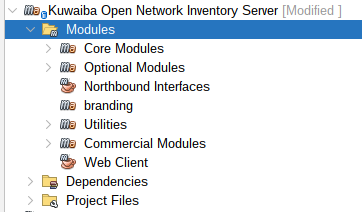 |
|---|
| Figure 1: Kuwaiba Modules |
Create a Java application with Maven and name it as you prefer (In this example, it was named RentHouse):
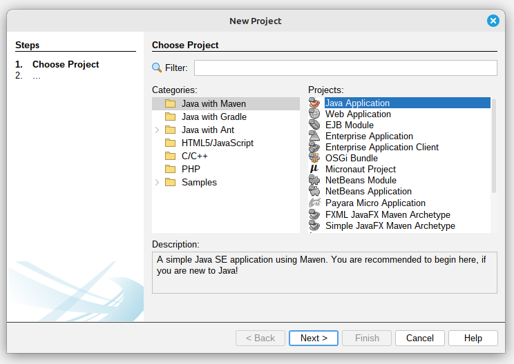 |
|---|
| Figure 2: Creating a New Project |
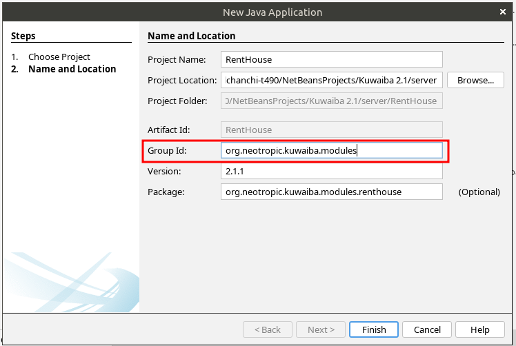 |
|---|
| Figure 3: Add the Group Id |
Your Project:
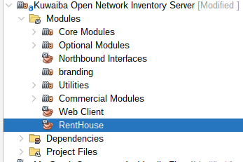 |
|---|
| Figure 4: Module Created |
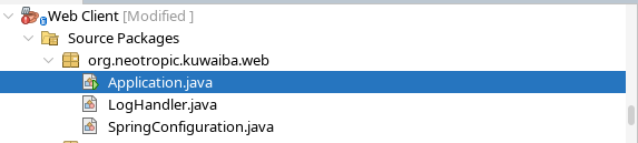
Web Client
In the main Kuwaiba application, we also have the Web Client, which serves as the entry point for the entire project.
Open the Web Client Application in the Main Kuwaiba Application:
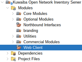 |
|---|
| Figure 5: Web Client |
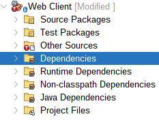
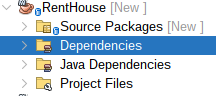
Right-click on Dependencies and then click on Add Dependency:
 |
|---|
| Figure 6: Web Client Dependencies folder |
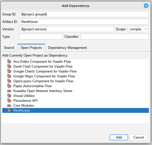
Select your project and add it to dependencies:
 |
|---|
| Figure 7: Web Client Dependency Added |
Note
You can also add the dependency directly by editing the pom.xml file.
Module Structure:
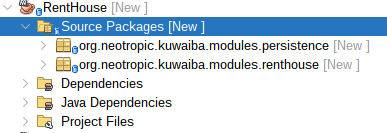
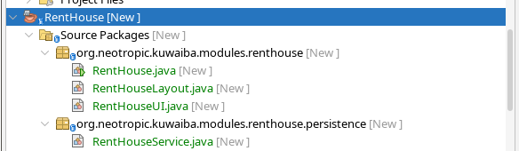
Create the following Packages within the Source Packages of your Module:
- persistence.
- (
Your module name), for this example renthouse.
Note
Verify that your Packages follow this structure:
org.neotropic.kuwaiba.modules.YOUR_PACKAGE
 |
|---|
| Figure 8: Rent House Packages Structure |
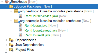
Create the following Classes within the previously created Packages:
 |
|---|
| Figure 9: Classes of each Package |
- persistence
RentHouseService: The RentHouseService class is a Spring service component to facilitate interaction with inventory objects.
- renthouse
RentHouse: The RentHouse class is a Spring component to define a specific module within the Kuwaiba application.RentHouseLayout: This class is designed to define the layout structure for the Rent House module.RentHouseUI: The RentHouseUI class is a Vaadin UI component designed to provide the user interface for the Rent House module.
Later, we will write the code that should go into each class.
Persistence API
Contains the definition of the classes and interfaces necessary for communication with the database. For this purpose, Kuwaiba uses the Persistence API, which allows you to manage data in the database.
Open the Persistence API Application in the Core Modules of the Main Kuwaiba Application:
 |
|---|
| Figure 10: Persistence API |
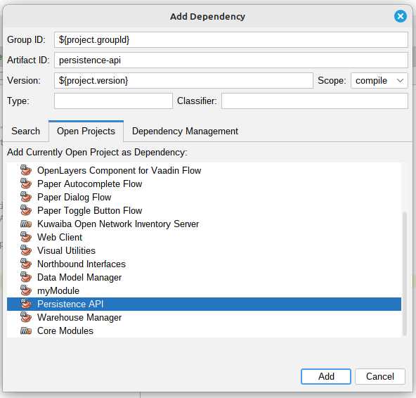
Add Persistence API to your module dependencies, right-click on Dependencies and then click on Add Dependency:
 |
|---|
| Figure 11: RentHouse Dependencies folder |
Select Persistence API and add it to dependencies of your Module:
 |
|---|
| Figure 12: Persistence API Dependency Added |
Note
You can also add the dependency directly by editing the pom.xml file.
Consume the Kuwaiba service:
BusinessObject and BusinessObjectLight
Since Kuwaiba's data model is dynamic, the system allows you to create any object you need to manage your inventory, providing high flexibility and customization in its administration.
In Kuwaiba there are two types of Classes to create inventory objects:
BusinessObject: It's a class that is used to map the inventory objects.BusinessObjectLight: It's the super class of Business Object.
BusinessObjectLight allows you to manage objects with the essential attributes of an entity in the database, such as id, name, and className. On the other hand, BusinessObject also includes these basic attributes and allows you to create objects with additional attributes, such as the creation date.
For the implementation of the example, we will use BusinessObjectLight to display the houses registered in the inventory, along with their basic attributes: id, name, and className. But first, we must understand some other concepts, which will be explained later.
Entity Manager Interfaces
They are interfaces that define fundamental operations and interactions with different aspects of the system. In Kuwaiba, there are three types of Entity Managers, each serving a distinct purpose:
MetadataEntityManager:Responsible for data model manipulation.BusinessEntityManager: Used to manipulate inventory objects, including adding, removing, updating, and retrieving items from the inventory.ApplicationEntityManager:Responsible for everything related to the application, such as user management and session handling.
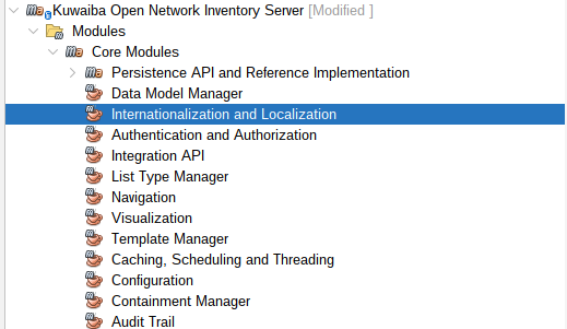
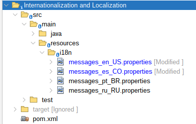
Internationalization and Localization Module
It's used to manage and adapt the content of Kuwaiba to different languages and regions.
 |
|---|
| Figure 13: Internationalization and Localization Module |
Modify messages_en_US.properties and messages_es_CO.properties files:
 |
|---|
| Figure 14: Internationalization and Localization Module Structure |
Add the following content in the messages_en_US.properties file:
    module.rent.house.name=Rent House Module
    module.rent.house.description=Rent House Module description...
    module.rent.house.title=Rent House :: Kuwaiba Open Network Inventory
Add the following content in the messages_es_CO.properties file:
    module.rent.house.name=Renta de casas
    module.rent.house.description=Renta de casas descripcion...
    module.rent.house.title=Renta de casas :: Kuwaiba Open Network Inventory
Translation Service
This interface provides translation services.
    @Autowired
    private TranslationService ts;
Use the Translation Service:
    public String getTranslation() {
        //Use the key from the internationalization file that you added
        return ts.getTranslatedString("module.rent.house.name");
    }
We will need the steps used in Internationalization and Localization Module and Translation Service later.
Now that we have covered the previous concepts, let's begin writing the code for each class.
First, we will create a module containing the basic code required for our implementation. At this stage, it will only include an empty interface. Next, we will walk through an example that involves the BusinessEntityManager
Insert the following code into your Module Class (RentHouse.java):
    @Component
    public class RentHouse extends AbstractModule{

        public static final String MODULE_ID = "renthouse";

        @Autowired
        private ModuleRegistry moduleRegistry;

        @Autowired
        private TranslationService ts;

        @PostConstruct
        public void init() {
            // Register the module itself
            this.moduleRegistry.registerModule(this);
        }

        @Override
        public String getName() {
            return this.ts.getTranslatedString("module.rent.house.name");
        }

        @Override
        public String getDescription() {
            return this.ts.getTranslatedString("module.rent.house.description");
        }

        @Override
        public String getVersion() {
            return "2.1.1";
        }

        @Override
        public String getVendor() {
            return "Neotropic SAS <contact@neotropic.co>";
        }

        @Override
        public String getId() {
            return MODULE_ID;
        }

        @Override
        public AbstractModule.ModuleType getModuleType() {
            return AbstractModule.ModuleType.TYPE_OPEN_SOURCE;
        }

        @Override
        public int getCategory() {
            return CATEGORY_ADMINISTRATION;
        }
    }
Insert the following code into your Layout Class:
    // Use the basic Kuwaiba layout
    public class RentHouseLayout extends ModuleLayout{ }
Create an empty view inside your UI Class:
    @Route(value = "renthouse", layout = RentHouseLayout.class)
    public class RentHouseUI extends VerticalLayout implements HasDynamicTitle,AbstractUI {

    private final String MODULE_NAME = "RENT HOUSE BY: Neotropic SAS";

    @Autowired
    private TranslationService ts;

    private H3 title;

    public RentHouseUI(){
            super();
            setSizeFull();
    }

    @Override
    public void initContent() {
    createTitle();
    }

    private void createTitle(){
        this.title = new H3(MODULE_NAME);
        add(this.title);
    }

    @Override
    public String getPageTitle() {
        return this.ts.getTranslatedString("module.rent.house.title");
    }
}
Next, right-click on the module and select Clean and Build:
 |
|---|
| Figure 15: Clean and Build your New Module |
Now let's run the application. In the Web Client module, right-click Application.java and select Run File.
Once the application starts, you can access it in your browser at http://localhost:8080.
 |
|---|
| Figure 16: Run Application |
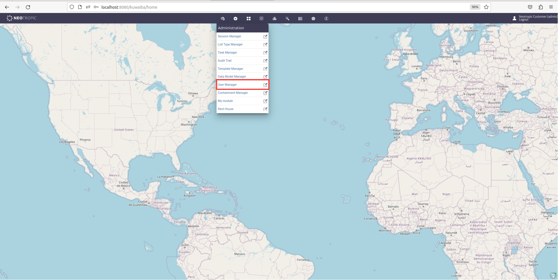
Enable your Module
Go to User Manager:
 |
|---|
| Figure 17: User Manager |
In the Administrators section, look for and enable your module for the Neotropic Customer (admin):
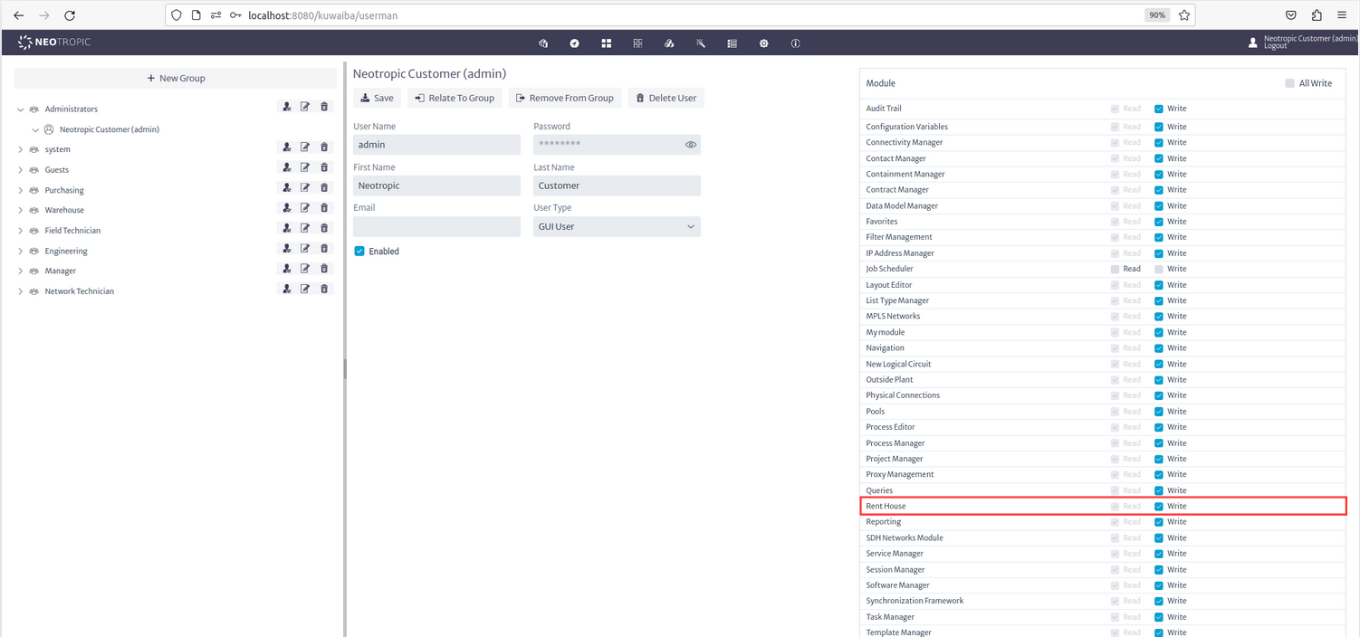 |
|---|
| Figure 18: Enable the Module |
Now you can see you New Module in the Administration section;
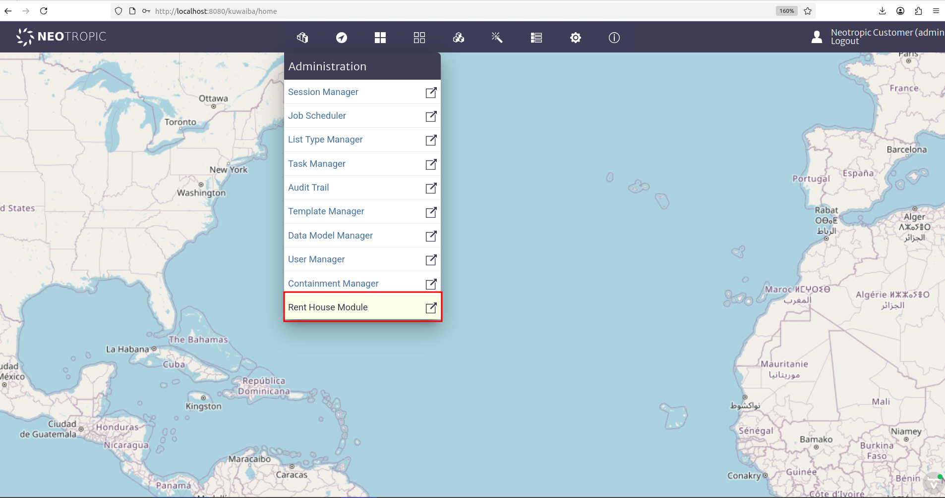 |
|---|
| Figure 19: Rent House Location |
When entering the Rent House module, you will see an empty interface that only includes the title we added in the UI
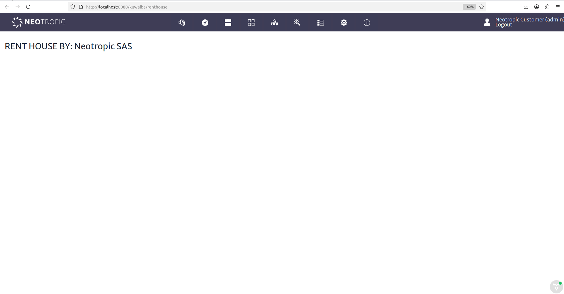 |
|---|
| Figure 20: Empty Rent House Module Interface |
Now we will include the use of BusinessEntityManager in our service class and update the UI in order to retrieve 10 houses from the database and display them in the interface.
Consume the service through BusinessEntityManager interface. Insert the following code into your service Class:
    @Service
    public class RentHouseService {

        @Autowired
        private BusinessEntityManager bem;

        public RentHouseService(){

        }

        public List<BusinessObjectLight> findAllBusinessObjectLight(String className,long page,int maxLimit )
                throws MetadataObjectNotFoundException, InvalidArgumentException{
            List<BusinessObjectLight> listObject = new ArrayList();
            listObject = this.bem.getObjectsOfClassLight(className, page, maxLimit);
            return listObject;
        }
    }
You can access the BusinessEntityManager interface to explore other services that Kuwaiba provides for managing inventory objects.
Create your view inside your UI Class:
    // renthouse is the route of your view
    @Route(value = "renthouse", layout = RentHouseLayout.class)
    public class RentHouseUI extends VerticalLayout implements HasDynamicTitle,AbstractUI{

        private final String MODULE_NAME = "RENT HOUSE BY: Neotropic SAS";

        @Autowired
        private RentHouseService rhs;

        @Autowired
        private TranslationService ts;

        private H3 title;

        private Grid<BusinessObjectLight> gridObjects;

        public RentHouseUI(){
            super();
            setSizeFull();
        }

        @Override
        public void initContent() {
        createTitle();
        createGridObjects();
        }

        private void createTitle(){
            this.title = new H3(MODULE_NAME);
            add(this.title);
        }

        private void createGridObjects(){
            try{
                List<BusinessObjectLight> objects = new ArrayList();

                objects = this.rhs.findAllBusinessObjectLight("House", 1, 10);

                this.gridObjects = new Grid<>(BusinessObjectLight.class, false);

                this.gridObjects.addColumn(BusinessObjectLight::getId).setHeader("ID");
                this.gridObjects.addColumn(BusinessObjectLight::getClassName).setHeader("Class Name");
                this.gridObjects.addColumn(BusinessObjectLight::getName).setHeader("Name");

                this.gridObjects.setItems(objects);

                add(this.gridObjects);

            }catch(InvalidArgumentException | MetadataObjectNotFoundException ex){
                new SimpleNotification(ts.getTranslatedString("module.general.messages.error"), ex.getLocalizedMessage(),
                        AbstractNotification.NotificationType.ERROR, ts).open();
            }
        }

        @Override
        public String getPageTitle() {
            return this.ts.getTranslatedString("module.rent.house.title");
        }
    }
Navigate to your new view:
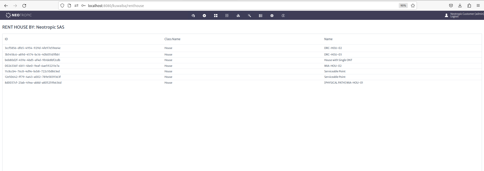 |
|---|
| Figure 21: Rent House View |